• Howdy! we're looking for donations to finish custom knowledgebase software for this forum. Please see our Funding drive thread

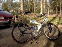
Bubba's 1st Bike Build

The Arduino is a micro controller. I using it to implement current limiting and current cruse mode by way of a PID algorithm. It was all working well on the trailer. It will work again when I have time to fix it. Here is a link to the Arduino site. http://www.arduino.cc/.

Bubba
 
i don't know much, but i am trying to build a simple electric bike, i am using; a Scorpion 4025-16, two 12v 38ah UPS batterys, a cheap rc speed controller and a cheap full suspension bike. i have found most of the bits i still need but i can't find a sprocket suitable for bike chain, can you tell me where you got the #40 sprocket from it would realy help

many thanks
human
 
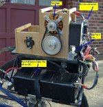
I hit the road for the first time today. Max speed was 30 mph. Everything was working well until the gear driving the southpaw freewheel decided to spin on its shaft. Still need to paint the rack, harden the drive shafts, make a cage for the gears, make a water proof cover, fix the arduino ... A mans job is never finished, but I am on the road!!!!!! After a few adjustment, I may try my Zippys in a 12S configuration. My jimmywu 36V (was 48V) piece of shit battery is just for testing.

Bubba
bike.jpg
left.jpg
right.jpg
 
Great day for ya!

At 48 volts you should be looking at about 40mph. Don't let the mtorocycle guys find out what you are doing. They will flog you (ask me how I know). :?

Anyway, I am lovin this bike. Very functional and purpose-built. The box turned out very well.

I like the "Active suspension". :mrgreen:

Matt
 
That's awesome.

I love the wood powertrain box.
I bet it's light and strong. I've been
considering wood to box the tube on my trike.
 
Hey is that a scorpion motor? How has that motor been working out for you? Any sync issues? What's the model number. I'm trying to find a good motor for my ebike.

Thanks,

Kin
 
My motor is an HXT 80-100. These motors have had problems with bad bearing, loose winding and loose magnets. I have only had the bearing problem to date. My approximately 300 mile experience with my trailer experiment, says they run hot. My suggestion, if you should go with this motor, is to immediately replace the bearings, check for loose windings and run at 36V. Should you have windings or magnet problems see liveforphysics thread for how he addressed the issues.

Bubba
 
What are you limiting the current to? I don't know what the gear ratio is, but I suspect you could easily get 40+ mph(Given the results I've been getting in my simulator) if the gear ratio is optimized and there's essentially no current limit. But since you're using jimmywu batteries(similar to pings, I suppose?), I suppose you're letting less than 1.5 kW through?
 
I was running at 36v and kept the amps below 60A because of the batteries. If I remember correctly, it was in the 20 to 25 amp range when going 30mph. Going to my zippys and 48V will get me to 40ish mph, but will be limited to 85 amps by my controller. I may gear it up for a speed run, but 30 mph is more then fast enough for every day ridding. Most bike wheels are not going to do well if you hit a pot hole at speed.

Right now I have things tore down while I paint the rack, harden the drive shafts, and do my taxes. When things are back together, I will post some data from the data logger.

Bubba
 
Do you believe that I remade the rack in aluminum or that I was too drunk to go to home depot and buy some other color of paint?

Bubba

 
It was fun while it lasted. I put the 12s zippys on the bike and was making 40mph runs. Charged them up for a second time and went for a slow ride to see how many ah I could get out of them. About 10 miles in I was going up a short steep hill, things just quit and that wonderful smell of burnt electronics wafted by.

Bubba
 
We need details!

Was it the CC controller that burnt out? I don't remember clearly, but I thought you had some kind of temperature sensing set up so how could it be a problem of too high a temperature? Otherwise, it seems the controller was designed to tolerate 60-110 continuous amps in partial throttle mode(depending on the cooling available to the ESC - 60 for an enclosed environment) and I can imagine the motor was probably consuming somewhere in the 100 to 200 amp region at the lower speed you were obtaining. See my e-bike simulator if you'd like more details about the current your motor was probably eating up at lower speeds(See the graphing feature) or, otherwise, just provide the following and I'll check and post the pretty graphs-

current limit:
wheel size:
Gear ratio(The amount of turns the motor takes for the wheel to turn once):
Voltage:
Internal resistance(I can guess):

Also, did you use extra capacitors? If so, how much? Also, was the appropriate battery capacity used for the current the controller was consuming? I think I remember the CC sheet saying to not use more than 75% of the rated current capability of the battery due to fluctuations that batteries can provide when stressed. If this might be related to this failure, than this will strongly dissuade me from upping the current limit on my ping batteries to 25 amps(even though I kind of want to!) which are rated for 20 amps.
 
The ESC was a CC 85HV. The attached graph shows ESC Temp (Temp A), Motor Temp (Temp B), pack voltage and amps. Death of the ESC happened at about 35 minutes into the ride. Temp was 110 deg F at the time. The amp spikes at the start are two speed runs. I think the motor temp has a lot of noise because the sensor wires run along the motor wires. It might have been temp that blew the esc. The heat sinks for the two fet boards do not touch. I filled the gap with heat sink grease, but it may not have been enough. There is also a recess in the top heat sink that I filled with a chunk of aluminum. I had a 1000 uF cap on the input.

Bubba
 

Attachments

  • cc85.jpg
    cc85.jpg
    265.2 KB · Views: 1,267
Interesting. It's only at 110F but yet it might have been temp? It sounds like a possibility the heat from the lower board didn't dissipate well enough when the motor current started increasing, as the thermal conductivity of thermal grease is quite poor compared to aluminum and copper so it's only effective below a certain amount of thickness(and why it's usually used for direct surface-to-surface applications). According to wikipedia, http://en.wikipedia.org/wiki/Thermal_conductivity, thermal grease has a thermal conductivity of 0.7 - 3 whereas aluminum has one of 220 (pure), 120--180 (alloys) so the thermal grease is effectively 100x less effective than aluminum foil and if I regularly experience a temperature difference of 10 degrees between the top and bottom(I used aluminum foil), it seems like yours could theoretically go up to a 1000 degree difference or more but it'd kill itself before getting to that point which it sadly enough seems like it did. (Interestingly, though, I thought castle creations said it would "cut itself out" if it went too high since the microcontroller would just temporarily malfunction. Are you positive the Castle Creations controller is still dead? Well, I guess the microcontroller could be been mounted on the top board so it would've gone unscathed anyways.)

I ended up putting aluminum foil between the bottom and top sink and I found the temperature difference between the CPU sink I added on top and the bottom board to be 20-25 degrees fahrenheit, with the difference between the top sink and bottom sink being around 10-15 degrees when the temperature was hovering around 160 degrees fahrenheit.

I also wonder if the added capacitance was enough, as well. I think recumpence ended up adding around 3000-4000 uF and I added 2000 uF and we both haven't experienced problems, yet(But, I also haven't been feeding the controller battery current above 20 amps, either.).

Anyways, nice grapher for temperature! Is eagle-tree some ultra-integrated ADC data logger of some sort?

If I'm reading it correctly, it looks like it was only drawing 15 amps before "cutting the battery current"(It appears to go to zero) but it seems like the temperature increases during the time of no battery current. Uh, so... that seems weird. Defined, it looks like the current cut out at 35 minutes but it looks like the temperature was increasing from 35-36 minutes. Assuming your temperature graph is correct, it also look like the amount of heat generation(properly called "heat" in physics) was greatest shortly before what I assumed was the malfunction at the 36ish minute mark, so that does seem to support your bottom-board-over-heating theory. It looks to be greatest there since the temperature-increase/time looks the greatest there, i.e., the slope of the temperature curve.
 
Here is a pic of the CC85 esc. I can see only two things with physical damage. The 3 pin chip near the esc wires looks like a small volcano erupted. The fet that split did not come unsoldered. It looks skewed because the top split off and slid to the side. The apparent cause may have been the little metal sliver between the black motor phase wire and the other little chip. The root cause would be me being sloppy. I will be sending the esc to cc for a repair.

Bubba

cc851.jpg
 
Bubba,

I am sorry to hear about your ESC failure. I have fried (I think) 3 HV110s myself before I figured out a few things. I am not an electronics guy, but I can tell you what I know from experience;

#1 Temp is critical with these controllers. I hit high current for only a few seconds at a time. This allows heat time to flow into the sinks. Fans are realy good to keep the controllers cool. The fans should blow at the sides of the heat sinks.

#2 Input capacitance (as mentioned earlier) is really important. I added two 1000mf caps to the input of my HV110.

#3 These ESCs don't tend to blow when teh abuse is occurring. They tend to blow with used lightly after the innitial abuse takes place.

I am sure you know these things already. But, I figured they were worth repeating.

Oh, I would recommend moving to an HV110 rather than another HV85.

Matt
 
Matt - That was a good recap. I think that I will step up to the cc hv 110 and give up on the idea of mounting it in a box for water proofing. The new mounting place will be in front of the fan cooling the motor.

swbluto - Yea, the metal sliver was foreign. Most likely it was the metal sliver that got me. The Eagle Tree is a data logger that is about a big as your thumb. The temp increase was because I didn't disconnect the power immediately. The vertical gray line is when power was disconnected and the temp started to come down.

Bubba
 
You may be correct that the metal fragment got you. That is truely a bummer.

I began carrying spare HV110s in case I blow more of them. However, now I have gone 400 miles without a problem (since adding caps and maximizing cooling). So, now I have two new controllers in the bag. I own 6 of them total. :mrgreen:

Great controllers! What I love most is the low speed response and the programmability.

Matt
 
If you need an esc, John at Holems Hobbies is the guy to see. He has good service and prices. My CC HV 120 came in today. Added the caps and repositioned it for max cooling. You can not see it in the picture, but there is a fan on the end of the motor blowing directly on the esc.

Bubba
 
recumpence said:
Bubba,

I am sorry to hear about your ESC failure. I have fried (I think) 3 HV110s myself before I figured out a few things. I am not an electronics guy, but I can tell you what I know from experience;

#1 Temp is critical with these controllers. I hit high current for only a few seconds at a time. This allows heat time to flow into the sinks. Fans are realy good to keep the controllers cool. The fans should blow at the sides of the heat sinks.

#2 Input capacitance (as mentioned earlier) is really important. I added two 1000mf caps to the input of my HV110.

#3 These ESCs don't tend to blow when teh abuse is occurring. They tend to blow with used lightly after the innitial abuse takes place.

I am sure you know these things already. But, I figured they were worth repeating.

Oh, I would recommend moving to an HV110 rather than another HV85.

Matt

I think the difference between the HV 110 and 85 relates to cooling effectiveness, so I'd think you should be able to push an 85 beyond its bounds into "110 territory" with the proper heat sinking and cooling. I'm even willing to bet you could even supercede an HV110... actually, I know you can since I saw the tables on CC's special project page once.
 
Here's the data from the first test run with my new CC 120 HV esc with the 12s zippys. Looks like I have lots of voltage drop when I use heavy throttle. I am not sure what would be normal, but 5 volts seems excessive.

Temp A - ESC
Temp B - Motor

Bubba

Data.jpg
 
It looks like the voltage drop is about 4 volts on average when the difference in current is 40 amps on average(70 amps - 30 amps). This puts the estimated internal resistance of your pack at...

4/40 = 100 mOhms.

I don't know what the AH of your zippy pack is to calculate its "standardized internal resistance"(So I can compare it to another LiPo pack that ES has data for) or SDT (Shortest discharge time), but if you'll provide that, I can compare it for you or you can do it.

The page where this information(Data + formulas) is contained at http://www.endless-sphere.com/forums/viewtopic.php?f=14&t=9314&p=144568&hilit=standardized+internal+resistance#p144568 .
 
Back
Top