I too was curious about using 3d printed parts in a structural application. The surface looks "stringy", but when I milled into the pulley, it was solid. Maybe a couple % voids. It feels solid, just like a molded nylon part. I like it a lot. Without 3d printing, I would not have been able to try this pulley...Chalo said:Skaiwerd said:One old school method actually used a bike rim and somehow a belt was used with epoxy to mold the pulley using the belt itself to form the teeth, then removed. Sounds dirty. Once you start 3d printing the old dirty way seems so troublesome.
I've been making things out of metal for so long that I don't think I could settle on using filament-fed plastic for anything structural. I think I'd be happier in most cases with laser cut birch plywood. Or Durham's Rock Hard Water Putty. Whatever's stronger and stiffer than squiggled-together PLA or nylon.
It's like if I made a wish to a genie, and it was to be able to make anything I want, in any shape. And the genie says, sure-- but it can only be as big as half a loaf of bread, and it can only be made out of tree sap. I'd think, well... um, okay, better than nothing, I guess....
You are using an out of date browser. It may not display this or other websites correctly.
You should upgrade or use an alternative browser.
You should upgrade or use an alternative browser.
Calling all Belt Drive Experts
- Thread starter FZBob
- Start date
So I got things stuck together well enough to try out. I tensioned the belt as tight as I dared, ie as hard as I could push the motor without a jacking screw.
On my bike stand, running against the back brake (poor man's dyno), the belt ran fine up to 180 watts. It sounds very high tech. No chain rattle, just a whir which matches the motor sound. Unfortunately, above 180 watts the belt started skipping. About one tooth per crank (or belt) revolution.
I tried it up my steep driveway, and got the same results. 180 watts. It's pretty consistent.
I just ordered a couple of bearings and a shoulder bolt from McMaster to make an idler. I'm hoping that increasing the belt wrap from 135 degrees to 190 degrees will dramatically increase power handling.
I would prefer not to go any higher on belt tension, as I have concerns about stress fracturing my bike frame where the motor mount is bolted on. If I do need to go higher, I may look at a strut directly between the motor mount and the bottom bracket area, so that the stress is not transmitted through the frame.
Did you check the radial runout on the printed pulley. If it's off center by just a little, the belt tension may be changing as it rotates.
FZBob
If the bike moves, without totally shattering the 3d printed pulley, then I’d say it was a success. Improvements to come as you’ve mentioned. Glad you explained that the tensioner puts more teeth engagemeing at the belt and motor pulley. I hadn’t realized that previously.
If the bike moves, without totally shattering the 3d printed pulley, then I’d say it was a success. Improvements to come as you’ve mentioned. Glad you explained that the tensioner puts more teeth engagemeing at the belt and motor pulley. I hadn’t realized that previously.
fechter said:Did you check the radial runout on the printed pulley. If it's off center by just a little, the belt tension may be changing as it rotates.
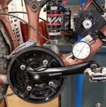
Good Call, Thanks!
The pulley was offset by .015" (inexpensive Shimano crank spiders were drilled offset from the rotating axis...). I opened up the holes and tapped it into position. The pulley is still oval (like a football) by .020 peak to valley. I wonder if it might have something to do with the "grain" of the printing process... Anyhow, since it is symmetrical I think it does not effect the belt tension so much.
Results - quick test on the bike stand. The belt held 535 watts, and the motor stalled. No slipping!
Grantmac
10 kW
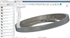
That CAD rendering with the inside ring gear has me thinking of an epicyclic reduction on the crank itself where the sun gear is fixed to the bottom bracket, the sprocket attaches to the planetary carrier and the motor drives the outside of the ring gear via a belt.
Getting it all sealed would likely be a pain though.
Getting it all sealed would likely be a pain though.
Skaiwerd said:FZBob
If the bike moves, without totally shattering the 3d printed pulley, then I’d say it was a success. Improvements to come as you’ve mentioned. Glad you explained that the tensioner puts more teeth engagemeing at the belt and motor pulley. I hadn’t realized that previously.
I don't think this pulley is going to shatter - it feels pretty rugged.
Here are some thoughts for improvements before I forget... I may have more observations after a few rides. If you would like me to do some DXF files, let me know...
I think it might be worth opening up the slots by about .005" or so, as the belt is a pretty tight press fit into the grooves.
It might also be interesting to drop the floor of the grooves down a bit, maybe .015 or so. I'm not convinced that the bottom of the belt needs to touch the bottom of the grooves. This might allow room for dust/dirt, and possibly make it run even quieter. Also, it would then be possible to turn a few thousandths off of the OD on the lathe for cleanup if desired.
I think some web sections could be reduced in thickness for weight savings.
By the way, can you mold in metal inserts, for instance aluminum sleeves where the mounting bolts go? Just curious...
Pretty cool to see the photo of the quage to check runout. I converted .02” to .508mm. Could prob build/print a centering jig to check as you drill out the holes. Or not.
To keep things simple and moving here perhaps the original creator of the pulley crank could help out with the changes. Qwiksand could you help out here?Your effort got things going here. You seem to be banging things out. I’m definitely among superiors as far as the CAD so we should utalize our talent the best. You guys are just better/faster.
Qwiksand if your up for FZBobs changes pm me for my email address and I’ll print the revision.
FZBOb I wouldn’t make the web thinner. The thicker the area printed the stronger it is, obviously. Maybe reduce around the outer edge? Think you mentioned that earlier. I can’t add anything that sticks up when printing, the print nozzle would most likely hit it. I could print pockets for nuts and print over the top of it, but I haven’t tried it
You could possibly use a standard metal chain ring and print a part that goes over it and bolt them together with a bunch of small bolts around the edge. This way the bolts have very low stress. The printed part would just be the teeth pretty much.
I'm not sure if it's possible to "print around" a metal insert but it would be nice. You might need two CAD files, one you print first that leaves sockets for the metal parts to lay in, and a second file to finish the rest. Either that or you pause the printing process at the right point to place the inserts. Epoxy might not be a bad thing around inserts. If you could embed a metal chain ring in the middle and print around it, the teeth on the metal sprocket would keep the parts from spinning.
I'm not sure if it's possible to "print around" a metal insert but it would be nice. You might need two CAD files, one you print first that leaves sockets for the metal parts to lay in, and a second file to finish the rest. Either that or you pause the printing process at the right point to place the inserts. Epoxy might not be a bad thing around inserts. If you could embed a metal chain ring in the middle and print around it, the teeth on the metal sprocket would keep the parts from spinning.
Ovalized chainrings are back in style, no? :wink:
While I suspect some of this variance is caused by cooling differences within the filament layers due to infill/print direction, the majority will be due to discrepancies in the steps/software rounding errors between the X and Y axis on the printer. 0.020" or roughly 0.5mm across a 190mm print is probably about the best we can expect to achieve with our hobby machines.
I can modify the file easily enough, adding a bit of clearance is no big deal. I've found with my skateboard pulleys, the belt tends to "wear in" the pulley as shown below:
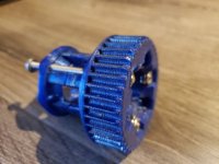
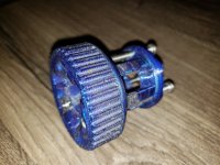
Little pebbles/road debris caught in the belt caused these dents, but doesn't seem to matter much:
View attachment 1
@FZBob, if you post up a dimensioned drawing of the hole/slot sizes you want (top view and a profile shot), I'll modify the pulley to suite. It doesn't need to have the tooth profile just use the outside diameter as a reference.
While we're on the subject of pulley modification, it might be interesting to take advantage of the additive manufacturing process. Below is a quick mock-up of some ventilation/clearance holes that can be easily made by any FDM printer, but would be incredibly tedious/difficult to achieve by traditional subtractive processes.
View attachment 5
View attachment 4
While I suspect some of this variance is caused by cooling differences within the filament layers due to infill/print direction, the majority will be due to discrepancies in the steps/software rounding errors between the X and Y axis on the printer. 0.020" or roughly 0.5mm across a 190mm print is probably about the best we can expect to achieve with our hobby machines.
I can modify the file easily enough, adding a bit of clearance is no big deal. I've found with my skateboard pulleys, the belt tends to "wear in" the pulley as shown below:


Little pebbles/road debris caught in the belt caused these dents, but doesn't seem to matter much:
View attachment 1
@FZBob, if you post up a dimensioned drawing of the hole/slot sizes you want (top view and a profile shot), I'll modify the pulley to suite. It doesn't need to have the tooth profile just use the outside diameter as a reference.
While we're on the subject of pulley modification, it might be interesting to take advantage of the additive manufacturing process. Below is a quick mock-up of some ventilation/clearance holes that can be easily made by any FDM printer, but would be incredibly tedious/difficult to achieve by traditional subtractive processes.
View attachment 5
View attachment 4

Wow, lots of very cool stuff here!
I test rode the bike up my driveway - over 400 watts and the belt felt good. Smooth, and I really like the sound.
After about 30 feet the set screws let go and the motor pulley walked off the shaft. The motor shaft is pretty scored, but I think it will clean up. It really shows how powerful these little motors are! Now I need to figure out how to keep the motor pulley from slipping.
I'm considering using the key. I did a quick back of the envelope on the force of the key pushing against the inside of the aluminum pulley keyway. The numbers look interesting...
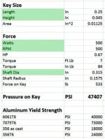
I'm pretty sure my cheap little pulley isn't 7075...
The Turnigy motors are only slotted for a 1/4" long key. I may need to lengthen the key slot substantially, and/or possibly add a second key to the other side of the shaft.
Those numbers really show why the set screws didn't hold!
I test rode the bike up my driveway - over 400 watts and the belt felt good. Smooth, and I really like the sound.
After about 30 feet the set screws let go and the motor pulley walked off the shaft. The motor shaft is pretty scored, but I think it will clean up. It really shows how powerful these little motors are! Now I need to figure out how to keep the motor pulley from slipping.
I'm considering using the key. I did a quick back of the envelope on the force of the key pushing against the inside of the aluminum pulley keyway. The numbers look interesting...

I'm pretty sure my cheap little pulley isn't 7075...
The Turnigy motors are only slotted for a 1/4" long key. I may need to lengthen the key slot substantially, and/or possibly add a second key to the other side of the shaft.
Those numbers really show why the set screws didn't hold!
I like this a lot. I think there is a fair chance it would handle dust and light dirt with minimal shielding. Lots of RC dirt cars have exposed gears which get pretty dirty.
When I get a bit of time, I would like to do some calculations on tooth loading, as unlike a belt or chain, the load is basically on single tooth at any given time...
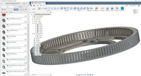
This is very cool!
Qwiksand -
I should probably get more data before you spend too much time making changes on my account... If I can solve the keyway issue, I may learn a lot over the next few weeks. As I learn stuff, I'll post it...
I can do various views and sections in Acad if they will plug into your software...
Grantmac
10 kW
Could a belt run on a pulley where the teeth are round pins? Just thinking about easier ways to machine one on non-CNC equipment.
Some of the pins would be bolts holding the whole thing together of course. Perhaps with 2 out of 3 teeth skipped it could work with a large pully.
Some of the pins would be bolts holding the whole thing together of course. Perhaps with 2 out of 3 teeth skipped it could work with a large pully.
Grantmac said:Could a belt run on a pulley where the teeth are round pins? Just thinking about easier ways to machine one on non-CNC equipment.
Some of the pins would be bolts holding the whole thing together of course. Perhaps with 2 out of 3 teeth skipped it could work with a large pully.
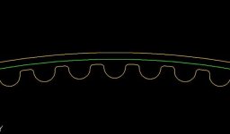
The tooth profile at the OD of the pulley is not really round, but has more of a flat top. That being said, on the large pulley I bet you could get away with all sorts of things. I wonder if a large smooth pulley with no teeth at all might work, or possibly just some non-skid tape or sander belt material. Kind of the inverse of Kepler's friction drive...
SlowCo
1 MW
FZBob said:I wonder if a large smooth pulley with no teeth at all might work, or possibly just some non-skid tape or sander belt material. Kind of the inverse of Kepler's friction drive...
That is what Mike has done. He has gone from grip tape to a rubber tape surface for his large rear "sprocket/wheel":
https://endless-sphere.com/forums/viewtopic.php?f=3&t=97578
I suspect that it might work fine up to a few hundred watts.
Grantmac
10 kW
FZBob said:Grantmac said:Could a belt run on a pulley where the teeth are round pins? Just thinking about easier ways to machine one on non-CNC equipment.
Some of the pins would be bolts holding the whole thing together of course. Perhaps with 2 out of 3 teeth skipped it could work with a large pully.
The tooth profile at the OD of the pulley is not really round, but has more of a flat top. That being said, on the large pulley I bet you could get away with all sorts of things. I wonder if a large smooth pulley with no teeth at all might work, or possibly just some non-skid tape or sander belt material. Kind of the inverse of Kepler's friction drive...
Tooth Profile.jpg
I think with a mill and rotary table you could easily machine a "skip toothed" pulley. So long as you have at least as many teeth engaged as there are on the small pulley it should be fine. The belt would simply lay on the pulley in between them and that friction would help as well.
For a purely friction surface I'd want to use a different belt profile with flat "teeth". The simplicity of that is very appealing for a low-ish powered build.
Grantmac said:I think with a mill and rotary table you could easily machine a "skip toothed" pulley. So long as you have at least as many teeth engaged as there are on the small pulley it should be fine. The belt would simply lay on the pulley in between them and that friction would help as well.
That's an interesting thought. Especially since I have a small mill and a rotary table... (I highly recommend having a cheap mill...)
As you are skipping teeth, you could probably approximate the .118" dia cut with a 1/8 end mill. The .018" radius chamfers up top would be difficult, but I might just hit them with a file and call it good.
My experience with the rotary table is that nothing is "easy"... :lol: A better description would be painstaking and stressful, but very satisfying. Think of a long afternoon reading 3 digit numbers off an Excel sheet, counting hash marks on the RT, and double checking everything. Compared to that, 3D printing seems like magic.
Grantmac
10 kW
Easy is always relative of course. I'd just make the teeth short enough to not need a precise chamfer then do as you suggest. It would mostly run on friction with the teeth there for wet weather etc.
I'm almost ready to jump on 3D printing but not quite yet. In 5 years we might be scintering at home.
I'm almost ready to jump on 3D printing but not quite yet. In 5 years we might be scintering at home.
To keep the motor pulley in place, what I do is use two set screws at 90 degrees. A single one will never stay tight. If the pulley only has one, you need to drill and tap for a second one. Place the pulley on the shaft and tighten the screws, then remove it and look for the marks on the shaft. Then take a dremel tool or round file and make divots in the shaft where the screws will touch. A little blue Loctite on the shaft helps.
I've done this on several high powered setups and never had one come loose. Once I had a controller short while the wheel was blocked and it was able to rip the teeth off the belt.
I've done this on several high powered setups and never had one come loose. Once I had a controller short while the wheel was blocked and it was able to rip the teeth off the belt.
I decided to use a key. Here is a cheap but time consuming way to cut a keyway. First I slotted the bolt to use as a guide. No reason for the threads, just the first thing I found that fit the hole.FZBob said:After about 30 feet the set screws let go and the motor pulley walked off the shaft.
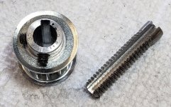
Coping saw for the rough cut.
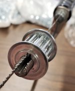
Jewlers file to finish. After 2 hours of filing with a fine jwelers file, I discovered that I had a coarse file...
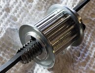
I made a wider and taller key to spread the load in the aluminum pulley. Would have been nice if the Turnigy motor had a full length keyway
Looks like how I do things. Nice work.
What is the shaft diameter?
On one of my motors, the shaft was about 5/16" and the pulley looked very similar to yours. The set screws were drilled right into the teeth on the pulley so it was mid way between the flanges. This allowed for the set screw to be fully engaged and didn't seem to bother the belt.
I haven't use many shaft keys, but it seems like it should work. I recommend Loctite on the key and between the shaft and the pulley. Not so much on the set screws if you ever want to get it off again. The idea is you don't want any wobble or free play at all or it will just loosen itself.
FZBob
Great hand work there. I don’t think I’d have the patience to do that accurately. I’ve been looking for pulleys for my future build but in the larger 8mm pitch. I found a distubtror of pulleys where the center bore and keyhole size, and set screw, can be customized.
The link below is for the size revaant to the original topic. FZBobs low power rc middrive build, single stage reduction, that uses a 5mm pitch x 15 mm wide belt.
https://www.beltingonline.com/12-tooth-htd5-pulley-12-5m-15f-7708
If anyone knows of a similar business in the USA please post a link. Sometimes local is faster and cheaper, but not always.
This may help some who are looking for a custom pulley.
I got the bike running with the big key in the motor shaft. Works good on the stand, but the belt is slipping at over 200 watts riding up the driveway. This time, the slipping is pretty random. The belt is tight, and the pully is centered. Hmmm. 
Looks like it's time to try an idler pulley...
Looks like it's time to try an idler pulley...
VESC Controllers on sale - $85. I like this controller a lot, and it has run without any problems...
https://diyelectricskateboard.com/collections/esc-speed-controller/products/torque-esc-bldc-electronic-speed-controller
I'm ordering one as a spare, and possibly motivation to convert my other bike or my wife's bike...
https://diyelectricskateboard.com/collections/esc-speed-controller/products/torque-esc-bldc-electronic-speed-controller
I'm ordering one as a spare, and possibly motivation to convert my other bike or my wife's bike...
Similar threads
- Replies
- 20
- Views
- 2,095
- Replies
- 2
- Views
- 948
- Replies
- 5
- Views
- 693
- Replies
- 2
- Views
- 10,796

