fechter said:
Not much. They stay pretty consistent over their life. That ratio looks pretty close to what I had on my old Vego. Proper belt tension is quite a bit.
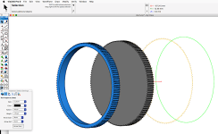
Vego belt drive.jpg
Are you going to have a freewheel between the pulley and the crank? Might be dangerous if the motor runs and the feet are not in sync.
That looks like a cool toy! 5mm pitch belt? Do you happen to know how many teeth on the motor pulley? How many watts?
No freewheels for me!

Eliminating the freewheel makes the assist extremely nice to use. Some trails that I ride require constantly varying accurate power levels, both leg and motor. As my motor is always spinning, I can bring on power very smoothly and precisely. The power is just there - instantly. There is no backlash and "clack" as the freewheel takes up, which tended to upset the bike in the technical stuff. I had a freewheel on the initial build, and I would never go back!
Also, parts which are not there don't break or add weight. The motor drag when pedaling is only about 6 watts!
I have about 500 miles of technical mountain biking with the chain drive running direct, and no real problems. A couple of instances where I was clocking the pedals to get through rock gardens, got a little uncoordinated, and I could feel the pedals push a bit, but my legs can easily stall the motor. But that is out of hundreds of chances... That being said, I would NOT run direct with any more power than I have.
I am very cautious when the bike is in the work stand with the battery installed, as I'm sure the pedals could break a hand or crack a skull. Also, when I'm walking up steep loose hills and using a bit of power to help, I have smacked my shins a few times - derp...
Time for the obligatory
Internet disclaimer -
Don't try this at home! You could bruise a shin, get tossed over the handlebars, loose control and hit a car, burst into flames, etc. It's the end of the world as we know it... and i feel fine...! (REM) :lol: