Charge fast by paralleling with a full charge battery.

Joined
Apr 25, 2014
Messages
2,803
Location
Sausalito
At full it’s 87v 11.4ah.
Lifepo4. 24s3p
K2 26650 3800mah cells.
Continuous Discharge rate: 12A (4c)
Pulse 30 Seconds Discharge: 28A (8c)
Charge Current: 3.8A (1c)


The rated charge current is low but surely can be charged faster and cause little loss up to maybe 80% capacity, no?

I planned to get the battery resistance doing this:

https://www.instructables.com/How-to-measure-the-internal-resistance-of-a-batter/

And add a resistor between the batteries to limit the charge current.

I have a charger that does the max the cells are stated to take but maybe in an emergency I could parallel the battery to charge at 40amps to 80%? How bad is that for the cells? I’ve never seen a graph of fast charging w lifepo4. Can it be dangerous, and at what point?
 
You absolutely sure you want to risk this?
However, if the battery you are charging FROM is much smaller, than voltage will sag, voltage delta will drop and the process will be self-limiting.
If you add a resistor, it will likely heat up cosiderably and cause *large* losses!

Just play with IR formula to determine currents and voltage drop given internal resistance of both batteries... but I think you want one of those boost converters that work up to 90v and can take 30A of current.

Now that I think about it, it should be fairly safe (perhaps even TOO safe, ehehe) with lifepo batteries (provided that BOTH are lifepo) even with similar capacity due to very flat discharge curves, so you'll have very little voltage delta to play with.
 
BalorNG said:
You absolutely sure you want to risk this?
No. I think my charge port is too limiting anyway but wonder for the future how fast could charge and with what degradation. I’m assuming it’s safe enough.

Yea maybe too safe and prompts me to abuse my battery. I’ll have to try with just two cells n see how it goes.

Can only charge to 50% capacity obviously and yet forgetful, making it less stress on the cells I guess
 
Hummina Shadeeba said:
I planned to get the battery resistance doing this:

https://www.instructables.com/How-to-measure-the-internal-resistance-of-a-batter/

Do not proceed unless you get the same reading twice.

That is not " IR testing" in my opinion . That is " I wish i could IR test but I dont have the equipment so I am gonna do this and get results all over the board and they wont be accurate at all but I will use thes flawed results to make me think I am doing something accurate"...

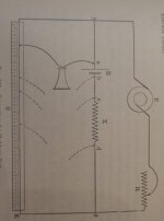
You would be better off with Sheldons Test. All ya need is a slide resistance, a telephony bell, a induction motor at 333rpm, and a battery to test. Dont even need a multimeter if you are good enoug ( they did not have those in 1863).... ( but they took 1000hz AC readings of the internal resistance of a battery reguardless.. even they didn't mess with that " dc resistance testing" back then... They wanted "good " " repeatable" results... )

IR should only be taken on charge form 30% SOC at room temp... First thing you negate in your procedure is taking an IR reading upon a discharge ( as the instruct able tells you to) .

Hell yeah LiFePo4 takes a high charge rate. It beats them up in the long run though.

Sheldons test: ( sorryt he "instruct able" for "Sheldons Test " were lost, to time, a little while ago,... You might have a hard time finding the procedure)...
 

Attachments

  • SheldonsTest.jpg
    SheldonsTest.jpg
    65.4 KB · Views: 317
Hummina Shadeeba said:
I have a charger that does the max the cells are stated to take but maybe in an emergency I could parallel the battery to charge at 40amps to 80%? How bad is that for the cells? I’ve never seen a graph of fast charging w lifepo4. Can it be dangerous, and at what point?

Are the two packs the same capacity? If so, wouldn't you end up with two packs charged to 50%? (Or until the two packs are at the same voltage)
 
There are multiple potential fire hazards with this, depending on factors you don't specify (resistance, etc):

If you connect a non-current-limited source (battery) to another battery that is at a lower voltage, the current is only limited by the total circuit resistance and the difference in voltage.

Let's make it simple and say you have two identical packs as you describe, and assume each has identical 500milliohm total resistance (they wont be identical, and it's different at different states of charge) for a total of 1ohm total resistance. One is full 87v, one is empty at 67v, so a 20v difference.

20v / 1 ohm is 20A. Voltage will sag some on one and rise on the other, dropping the current a bit, let's say it drops to 18A for simplicity. 18A charge current across 3 cells is 6A each, so nearly twice the specification's charge current, meaning twice what the cells were intended to take. That will cause heating within the cells, by how much I don't know, but it could be at least twice as much as there should be.

If it's only 11Ah and that is the difference in state of charge between the packs, the high current won't last all that long, because you'll only get about 5Ah (assuming significant loss of power as heat) out of the full pack into the empty one, but the heat generated in the cells could still do damage--if it is enough to cause a fire eventually, I don't know. It depends on the actual resistance, actual heat, and what kind of cell damage is caused by the nearly double charge currents, condition the cells started in, and how long the excessive current lasts.

If the cell and interconnect / etc resistance is a lot lower than the 500milliohm SSWAG I used, the current will be higher. Let's say it's half that...taht means the current will be double, 40A, whcih means four times what the cells were meant to take. Etc.


If you have a BMS on the packs, then the charge port of the BMS on the low pack must be designed for and capable of the highest charge current you'll use. If it is not, the FETs can fail in several ways, from catastrophic exploding to just unsoldering themselves from the heat (leaving solder blobs and/or parts floating in the BMS and/or battery pack to short things out) or most commonly in a way that then does not show externally, but leaves them stuck on. If that latter mode happens, the BMS cannot ever stop charge even if there is something wrong with a cell that will cause a fire (overcharging, overheating (assuming temperature sensors in the pack and BMS that can read them) etc). That means there is not just a fire risk from the FETs themselves if they should overheat enough to fail catastrophically, there is a risk that a silent failure could lead to cell damage and overcharge over time that could lead to a fire.


If the charge port wiring, connectors, crimps, solder, interconnects, etc., are not all rated for and capable of handling the max current, then they too are at risk of damage that could lead to a fire.

There was something else but I forgot what it was while typing the above.
 
Hummina Shadeeba said:
I’m assuming it’s safe enough.

Never assume that doing things to a cell that it was not designed for are safe.

It's a good way to kill people and destroy things.
 
The two batteries are the same capacity so yea will only charge to 50% capacity.


I’ll try with just two cells put in parallel w no added resistor.

I think the stated charge rate is conservative and if charging to a low soc higher charge rates maybe have minimal effect. I’m sure someone has done this and graphed it and was hoping someone knew where this info was so I’m not finding out myself.
 
Lots of small, cheap, and efficient DC-DC converters exist to accomplish the same goal, but safely and with constant current. Some of the small cheap DC-DC converters I dyno'd for efficiency exceeded 99%. This enables the whole system size and weight to be smaller as it doesn't need thermal dissipation for high power resistance to shed V-drop.
 
A K2 cell is different from headway and there's A123 and ping's cells.and his improvements all lifepo4 all different animals.
Meaning the quality of cell matters.
And don't do it.
 
Back
Top