Connecting ebike controller (ignition wire and thumb throttle wires)

ChrisAPal

1 µW
Joined
May 18, 2020
Messages
3
Hi All: I starting to get lost connecting my cables to the controller/battery and hub. I'm hoping someone with knowledge can do a sanity check on this for me and provide simple instructions on wiring everything up. A simple wiring diagram would be nice but I can't find anything online that I can understand. I've attached pics of my system parts:

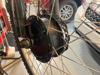
350W front hub brushless motor (I don't believe this motor Hall Sensors) it's Hill-Topper hub motor
Thumb Throttle, (I don't want Peddle Assist or Dash Display)
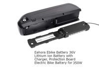
Eahora 36v Ebike Battery
36v Controller

My questions are regarding the Ignition wire from the controller and the thumb throttle connection steps. Can you please answer each question if you know the answers or provide a drawing of the wiring to connect everything together, also feel free to provide a sanity check and/or insight on what I'm doing?

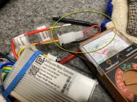
1 - I have tagged all the wires coming out of the controller and have them all figured out to the best of my knowledge, except for how to wire the ignition wire/s and the throttle wires. (see photos). The Ignition has 2 wires (red and yellow) with a jumper. Do I remove the jumper? A step-by-step on how to deal with the ignition wires would be helpful.

2 - I believe the ignition (red) wire goes to the on/off switch/key switch, then from the switch I think I run it to the battery positive and back to the (yellow) ignition wire on the controller. Is this correct?

3 - The throttle has 3 wires coming out of the controller. Where do I connect these 3 speed controller wires and please be specific? I guessing they go to the throttle wires is that right? I haven't received the throttle I ordered yet. Not sure if it has two or three wires.
 

Attachments

  • Slide1.JPG
    Slide1.JPG
    150.9 KB · Views: 2,616
  • Slide2.JPG
    Slide2.JPG
    91.5 KB · Views: 2,613
  • Slide3.JPG
    Slide3.JPG
    39 KB · Views: 2,604
  • Slide4.JPG
    Slide4.JPG
    119.4 KB · Views: 2,613
ChrisAPal said:
The Ignition has 2 wires (red and yellow) with a jumper. Do I remove the jumper? A step-by-step on how to deal with the ignition wires would be helpful.

Your picture shows "5v" on that jumper.

If the "ignition" wire is a 5v, that would be unusual. All I have seen are full battery voltage. If you hook something only intended to be carrying 5v to the battery voltage you'll probably destroy the controller *and* everything else hooked up to it that runs on 5v (including the motor's hall sensors, throttle, etc, if they're attache at the time). If you read 5v on that jumper wire, it is probably not the KSI line.

Normally the "keyswitch / ignition" / KSI wire is connected to the battery positive to turn on the controller. This can be done directly, or thru whatever type of switch you prefer to use.

There are a lot of posts about "KSI" "keyswitch" "ignition" "door lock / doorlock" etc, for many different controllers, that may help with the wiring. There are also "brainpower" controller posts that may have useful information.


3 - The throttle has 3 wires coming out of the controller. Where do I connect these 3 speed controller wires and please be specific? I guessing they go to the throttle wires is that right? I haven't received the throttle I ordered yet. Not sure if it has two or three wires.
If it's a two-wire throttle it is probably a potentiometer or just a switch, and wont' work on this controller without additional components (at minimum, specific setup of resistors or else active electronics).

If it's a three wire, there are a lot of threads about "throttle wiring" and "wiring a controller" and the like that show various ways the many different controllers and throttles may connect. There are also "brainpower" controller posts that may have useful information.

There's no guarantee that any particular wiring pattern will be the same for any throttle or any controller, so whatever we tell you or you find here may not apply to your controller (we have no way of knowing if it will work or not).

In general, if both throttle and controller's throttle connector have a red and a black wire, then those will connect color to color (but not always). Then usually the remaining wire on one connector (which could be any color but is often green or white) will connect to the remaining wire on the other connector.


Wiring a controller may take trial and error, which should not (but could) cause damage to components.

It *will* cause damage if you connect battery voltage to low voltage circuits, so once the controller is powered on, you should measure every wire relative to battery negative, and note down any wires that carry higher than 5v, and don't connect those to anything unless you're very sure what they are for and that they can take that.
 
Regarding the questions in your picture comments (whcih I missed the first time around because they are not in your actual post):

This is the battery I'm using. Will it turn on without the ignition wire tapped to the positive output through a switch?
The ignition does not turn on the battery (just the controller). If the battery has a switch, then that siwtch turns it on. Otherwise it is always on except when the BMS shuts off it's output due to overdischarge or other problems.

This is the hub motor I'm using. it only have a 3 pin plug. I'm guessing these 3 pins connect to the 3 motor phase wires on the controller? Is that correct?
Generally, yes.

However, the controller you have pictured says on it an "angle" which means it uses hall sensors. It does not say on the label that it can run sensorless. So if it cannot, then it will not work with a motor that only has phase wires, and no hall sensor wires.


You may wish to recheck the connector on the motor, to see if it is actually three large pins in the middle, and several small ones around it, or several small recesses in the ring around it that have metal contacts in them.

If so, then you would need the matching connector to wire up to the controller (easiest way), or have to cut off all of the connectors on motor and controller phase/hall wires, and put your own connectors on both, or directly crimp or solder them together.
 
Kind thanks for your comments and expertise amberwolf: I need to break this down to respond accurately to you. I've worked on bikes for years but have only been working on ebikes for a short while...

1 - You are 100% correct about the ignition wire being FULL BATTERY voltage and not 5 volts. After reading your comments I took the loop wire off and tested it (36 volts) wow, thank you for that!!!!

I'm the person that marked that "ignition wire" 5 volt out of ignorance from wire drawings I saw online The graphic of the connectors on Amazon, didn't show or explain that wire and loop,,, After removing the loop, I can't get the controller to come on or the motor to spin, again Thank you for that!!!

My controller graphic wires.jpg

2 - The battery does have an on/off switch. But I actually ordered a Motorcycle Key Switch for the looped ignition wire and will mount it on the bike for added extra security.

3 - The Motor Cable Connector for sure, only has 3 wires. I provided pictures below.

Female hub connector.JPG

Here's the male plug:

Male hub connector 3 pin.JPG

4 - I don't think this motor has hall sensors - would the 3 only phase motor wires be an indicator of no hall sensors?

5 - can you recommend a control that's easier to connect?

I don't have the throttle I ordered yet but I can get the motor to run by using the learning wires. SO I'm really close and nearly there... any tips on a good controller would be appreciated. I don't need any gadgets like PAS, display unit, lights or brake switches... I want just a really simple set up. Again thank you for your time and kind assistance, I will check the other treads you mentioned.

Chris
 
If the controller will run the motor sensorless with the learn function, then it will run it with throttle. So you won't need a different controller to use the motor (unless something else goes wrong).

"Easier to connect" controllers are really only going to be ones that come as a kit with a specific motor, throttle, ebrakes, PAS, display, etc. (whichever of those items you intend to have on the bike) and prewired with plug-and-play connectors that already match, and can't be plugged in wrong.

Many "kits" don't have that (and may even require that you cut off completely mismatched connector types just so you can hook any of hte bits up at all!). :(

Some places like Grin Tech, EM3EV, etc., use a standard connection method with all their items, so anything that is compatible will just plug in. But they're more expensive to buy from by quite a bit than the generic "ebay" stuff out there. Generally more reliable, and generally better support...but for many people the cost difference is not worth it. (it is to me, but I only recently started earning enough to be able to afford Grin's stuff directly (rather than used)).


You can simulate a throttle signal with a small battery. AA or AAA (or C or D) size are about 1.5v, so assuming your throttle connector uses black for ground, red for positive, and green or white for signal, then the negative of the battery goes on black, and the positive goes on the signal wire (red stays unconnected). When you connect the positive to signal, the motor will begin to spin at probably about half speed in whichever direction the learn wires set when they were last connected.


However, if the controller has a PAS (assist) connector, it is possible that it *requires* the PAS input to have pulses at a certain rate (pedalling above a certain cadence) before it will begin allowing the throttle to work at all. Some are made that way. So if the above simulation test doesnt' work, that's the most likely reason why.

Some controllers will simply accept either PAS or throttle, where PAS detecting *any* pedaling just gives full output of whatever "PAS level" the controller is set to at that moment (without a display, there's no way to know or change that level, and many controllers don't support a display; this one probably doesn't, so it's just whatever the factory set in it). The throttle, if present, overrides the PAS, giving whatever level of power (speed, really) that you demand via throttle movement.
 
Good points thanks!

hahhha ,,, Interesting that you mentioned Grin. I almost bought a whole kit from them.

I've watched a lot of videos/information from the owner Justin, he seems really knowledgeable and his products appear to be super high quality. I did't mind the cost and was actually going to buy a kit from them because they've got a nice thru axle kit... But OMG their customer service and sales are brutal. They refuse to speak over the phone which can normally solve a problem or answers a question in just a few minutes, but they prefer to only work with customers through email. It takes them days to respond... after several days of dealing with email and I even corresponded with Justin himself,,, I gave up. If I'm going to spend that kind of money, I want to speak with someone to verify the specs of the components I want, beside, most of the items I wanted were out of stock anyway. Which I can't blame on them ,,, it's more likely not their fault with all of the covid stuff going on. Maybe I'll try them later, when this craziness is over. I actually like Hill Topper they answer the phone when I call and if not they always call me right back.

I really don't need a lot of power. I'm 64 YOA now,,, My goal is to have a little 350 motor that can help me get up tough hills. And key to me is I don't want the bike to look electric/modified.

Thanks for all of your time and kind assistance responding to my questions,,, I appreciate it.
 
Maybe I can help, I just installed the same controller, my motor, like yours, has no halls, just the 3 phase wires. It still works but will "shudder" far a second or 2 sometimes at startup, this is normal and giving a slight pedal boost upon starting minimizes this. Try and make sure the 3 phase wires match, you can look at you old controller to determine where each color went to which pin on the connector. My PAS connector fit into the controller but it did not work in PAS mode, not anything to me since I never used it in that mode anyway, probably could have been corrected by unsheathing my PAS cable and looking at the colors but anyway they will work without a proper PAS hookup as far as I can tell.
 
Butch1 said:
Try and make sure the 3 phase wires match, you can look at you old controller to determine where each color went to which pin on the connector.
When using sensorless (only phase wires) it makes no difference which ones are in which color order. That only matters if running with hall sensors, that you must have the right order of halls and phases to match.

With just phase wires, you can connect them in any random order.

If the motor rotates the wrong direction, just swap any two wires, and you're all set.

If it doesn't work, you have a problem somewhere else (connections, fets, etc).
 
Oh, OK I learned something new today then. With mine it initially started rotating in the wrong direction so I used the "self learn" wire and corrected it. I'm on the fence about these brainpower units, with the LCD display you have a lot of information but it's unclear how accurate it is. It says my MPH went up from 17-18 with the old unit to 20-22 with this one but it does not feel any faster. There is also a setting for current limit which I set at 13, what it's spece'd for, but during acceleration it says I'm pulling up to 20 amps. Then again, I do weigh 220lbs so maybe it needs that to get my fat ass moving LOL.
 
Back
Top