Correctly sizing Fuses for Battery pack discharge leads?

Joined
Sep 26, 2021
Messages
90
I'd like to put an inline fuse on the output leads of my battery packs for short circuit protection, just trying to figure out the correct fuse rating.

I'm using a Cyclone 3KW with the supplied 40 Amp controller at 48V 13S 7P Panasonic PF cells rated at 10A

So 70A max safe continuous output for the Cells, BMS is 60A though.


Motor Specs
* Max speed 900Rpm
* Rated speed 800Rpm
* Rated output 3000W
* Max output 4000W
* Rated Torque 50Nm
* Max Torque 100Nm
* Rated Amp 40A
https://www.cyclone-tw.com/product/6/data/17


I'm thinking one of these fuse holders https://www.ebay.co.uk/itm/143775556380?hash=item2179b0e31c:g:NIkAAOSwm8hffgsM

And 80A fuses
https://www.ebay.co.uk/itm/392405167271?hash=item5b5d2baca7:g:ciIAAOSwn1RXIkaQ


So 10 amps above the safe maximum of the cells in the pack, the fuse should blow.

Should blow fast enough in a short circuit to protect the cells from damage but without being too weak to handle burst current?


Have I got this right or should I go lower or higher for any reason?

Maybe the 60A BMS would need a lower rated fuse to protect it?


Or is there a better way altogether?
 
E-HP said:
I'd probably go with about 180A with the setup you're describing.

That's a chunky fuse! What kind of hardware would you use to put one of those inline on 10AWG wire?
 
E-HP said:
I'd probably go with about 180A with the setup you're describing.

In fact, what are the principles for correctly sizing a fuse for the battery pack on a setup? And some examples of the correct hardware to use?

As I'll be putting a guide together for the entire conversion process of my bike including all the things I needed to buy, as while there's lots of guides out there, none of them combine all the tips I've picked up along the way...
Like almost non of the guides I've read or watched mentioned NOT to spot weld the very center of the negative end of the 18650 can

As that's where the jelly roll is connected to the can by a Rail that runs the length of the battery....

And that for some reason BMS boards are more vulnerable to damage from Electro static discharge than the PC hardware you may be used to. And should be carefully tipped out of the packaging they arrive in onto an Electro static discharging mat and you will be wanting to wear an antistatic wrist strap with the attached wire connected to ground, like the bare metal inside a PC case with the power supply plugged into the mains....


And also don't go into other little tricks such as Die-Electric grease under the shrinkwrap where your wires are soldered to the connectors, to protect them from water, and salt kicked up from the road ect...
 
If you are using awg10 for wiring all the things I would take 60-80A fuse to protect the cables from short circuit.
Normaly if you can draw 50A continous , then your cable would be to small. But you only draw peaks, and you can´t heat the wires for an hour with your battery.
I do not know if it is possible to protect the BMS with a fuse.

Those inline fuse holders might be crap.
I used a similar looking but smaller one rated for 40A and with a 40A fuse (AWG10 wires on the holder) for my charge port.
With 35A charge current the fuse holder made 85C after 20minutes. I have got a 100Ah battery in my scooter.
Now I have a 50A fuse inline and sealed it up to the plastik housing with heatshrink tubing.
I have one with a higher voltage rating as my battery is 21S
But something like this will do the job.
https://www.reichelt.de/kfz-sicheru...MIs6CHm8zo9gIV2RkGAB123wuEEAQYBCABEgK_CvD_BwE
 
The fuse G wants is just about the worst fuse you can use for an ebike. Those plastic thin monstrosities are only good for 24v, and often melt when run near their continuous rating. If you run a blade fuse with a line ( wire) too small, the fuse usually melts first, with blade fuses. the plastic window is very thin,, and melts easily.

It is better to have a fuse higher than the expected current value because you do not want " Nuisance blows". If you put a 80A fuse on a line that takes 80A contin: you are ok.. but the peak WILL blow it one day, this is why more amperage within reason is recommended. I have a bike with a 50A contin and a 100A peak, with a 100A fuse, and the 100A fuse was very close to melting, from the blackened fuse link in my circuit. Very close to blow, on a "50A controller," from 100A peaks.

Unless the fuse is specifically a " SLOW BLOW" or " IGNITION PROTECTED" fuse, you want to design, for the peak current, the fuse may see, to keep nuisance blows to a minimum. A real ANL Ignition protected fuse cost alot: They begin at 25$ ea. and go upwards of 180$ ea for a single fuse.

dominik h said:
Those inline fuse holders might be crap.

But something like this will do the job.
https://www.reichelt.de/kfz-sicheru...MIs6CHm8zo9gIV2RkGAB123wuEEAQYBCABEgK_CvD_BwE
Yes, the inline fuse holder for the blade fuse is crap, poor construction, one time use, very poor. Y

Ou can get a bolt down MIDI enclosure, and have the integrity of bolts not spade terminal. They are small, also, only 1 inch long by about 1/2 inch wide.

Midi fuses?
Those are very good fuses, the MIDI line from LITTLEFUSE. They are native higher voltage design and can handle 58Vn easily. They are very small in volume, good for bikes, and have real body that takes heat and does not damage upon current application prematurely. Some even have a mica window. I use a 200A MIDI now on my bike, and a fuse holder that shows me a green, or red, light, based on fuse integrity.

498 Series - MIDI®
Bolt-Down Fuse

Also, Kontronic sells a fuse holder for this fuse, complete with indicator LED to show the fuse state! MIDI® Fuses are a cost-effect, space saving protection solution for high current wiring.

https://www.amainhobbies.com/kontronik-fuse-holder-kosmik-kon9061/p492630

https://m.littelfuse.com/~/media/commercial-vehicle/datasheets/automotive-fuse-holders/midi/littelfuse_fuseholder_inline_midi.pdf

kon9061.jpg
 
Gorillazilla said:
In fact, what are the principles for correctly sizing a fuse for the battery pack on a setup? And some examples of the correct hardware to use?

You said your purpose is for short circuit protection. Presumably that's to improve safety. So, if safety is the primary motive, then you also need to consider when you don't want the fuse to blow. The ones I think about are like crossing a busy 6 lane road or making a left at an intersection with oncoming cars. I don't want a fuse to blow in those situations, at the risk of becoming a grease spot on the road. However, for short circuit protection, you need a fast acting fuse, so it needs to be sized higher than any current you might encounter, absent a short.

My BMS is rated at 40A, but I pulled a 120A burst from it the other day, so if for some reason I wanted to add a fuse, I'd size it greater than that.
 
dominik h said:
I have one with a higher voltage rating as my battery is 21S
But something like this will do the job.
https://www.reichelt.de/kfz-sicheru...MIs6CHm8zo9gIV2RkGAB123wuEEAQYBCABEgK_CvD_BwE

Oh aye those look pretty good, I could just solder the battery wires straight onto the tabs then Heatshrink a few layers over as you say.

Pretty easy to replace if it ever blows, and only thing that should blow it is a short.

And they have a 175A version, pretty damn close to E-HP's suggestion and the fuse DogDipstick is using


E-HP said:
Gorillazilla said:
In fact, what are the principles for correctly sizing a fuse for the battery pack on a setup? And some examples of the correct hardware to use?

You said your purpose is for short circuit protection. Presumably that's to improve safety. So, if safety is the primary motive, then you also need to consider when you don't want the fuse to blow. The ones I think about are like crossing a busy 6 lane road or making a left at an intersection with oncoming cars. I don't want a fuse to blow in those situations, at the risk of becoming a grease spot on the road.


Good points, I was thinking about that actually, up a steep hill, especially if pulling a trailer as that might not go well with a loss of forward traction....
 
I think 175A is to much.
I have a 200A fuse and a controller which draws 165A continous, 175A peak on my scooter. I have driven 5000km without any issues.

Hold Time at 200% is 5 seconds for the fuses 125A and below. I don't think your controller will blow an 80A fuse under working conditions.

Just have a look at the datasheet.
https://www.google.com/url?sa=t&sou...AQFnoECAMQAQ&usg=AOvVaw1xYzGHesn5EzRA4lDBjvOx
 
E-HP said:
My BMS is rated at 40A, but I pulled a 120A burst from it the other day, so if for some reason I wanted to add a fuse, I'd size it greater than that.

But the OP's controller is rated only 40A, and won't draw significantly more than that. So if the battery 's current goes much higher than the controller maximum current plus accessory maximum current (lighting etc.), it means there's a serious fault condition. Personally, I don't see any reason to use a fuse value higher than 60A in this case, even if there are accessory loads.
 
Chalo said:
E-HP said:
My BMS is rated at 40A, but I pulled a 120A burst from it the other day, so if for some reason I wanted to add a fuse, I'd size it greater than that.

But the OP's controller is rated only 40A, and won't draw significantly more than that. So if the battery 's current goes much higher than the controller maximum current plus accessory maximum current (lighting etc.), it means there's a serious fault condition. Personally, I don't see any reason to use a fuse value higher than 60A in this case, even if there are accessory loads.

Understood. It's unclear to me on how different manufacturers describe the rated current vs the current limits. My controller is rated at 70A, 200A phase, but the battery amps go way past 70A in a burst (120A in my case). Max current can be set in the parameters in order to limit the current though.
 
E-HP said:
on how different manufacturers describe the rated current vs the current limits. My controller is rated a

Yeah mine too. Says " 50A " on the side, but will straight up pull 100A no prob many times in a day. On bursts and on peaks.
 
dominik h said:
I think 175A is to much.
I have a 200A fuse and a controller which draws 165A continous, 175A peak on my scooter. I have driven 5000km without any issues.

Hold Time at 200% is 5 seconds for the fuses 125A and below. I don't think your controller will blow an 80A fuse under working conditions.

Just have a look at the datasheet.
https://www.google.com/url?sa=t&sou...AQFnoECAMQAQ&usg=AOvVaw1xYzGHesn5EzRA4lDBjvOx

That's some smashing info right there, so to size the fuse correctly you need to size it so 500% of it's rating is the max that your battery can put out for one second without being damaged.

And to size it to protect the CELLS rather than anything else, because it's the cells that are the most expensive part of the battery. The BMS is only around $40 but the cells are more like $360


So I need to find out the max current a Panasonic NCR18650PF can put out for one second without being damaged at all. And then size the fuse to that.

The 10AWG wire should be fine as shown in this chart https://www.reddit.com/r/Nerf/comments/9iysnk/max_burst_current_for_each_wire_gauge_for_10/


Cheers chaps, great info and will go into any guides I make :bigthumb:
 
It is not so easy.
Your BMS, your wires, your connectors and your choosen fuse have an resistance/ impedance , they all together lower your batteries maximum current.

Edit : my single cell is 1.2mOhm. I have 5 in parallel and 21 in series. Impedance 5mOhm....

Wrong text [My single cell is rated 0.5mOhm , I have 5 in parallel and 21 in series. That should give me an impedance of 2.1mOhm.]


I measure 13.3mOhm directly at the controller which is still very good, but lower than calculated only with the cells.
Cell bus bars are 120mm copper and wiring is 32mm (awg2) and bigger.
 
dominik h said:
It is not so easy.
Your BMS, your wires, your connectors and your choosen fuse have an resistance/ impedance , they all together lower your batteries maximum current.

My single cell is rated 0.5mOhm , I have 5 in parallel and 21 in series. That should give me an impedance of 2.1mOhm. I measure 13.3mOhm directly at the controller which is still very good, but lower than calculated only with the cells.
Cell bus bars are 120mm copper and wiring is 32mm (awg2) and bigger.


Oh good thinking, what I mean though is the higher end of how much current can be pulled from a single cell for one second without damaging the cell

Then extrapolating that to how many cells you have in parallel to get the total amperage where you need your fuse to reliably blow in under one second

Not the max current that can run through the entire system theoretically, which IS effected by the resistance of the elements in the loop vs the voltage

The resistance of the BMS for example will not effect the amount of current needed to damage the cells will it?
 
Gorillazilla said:
Oh good thinking, what I mean though is the higher end of how much current can be pulled from a single cell for one second without damaging the cell

Then extrapolating that to how many cells you have in parallel to get the total amperage where you need your fuse to reliably blow in under one second

Not the max current that can run through the entire system theoretically, which IS effected by the resistance of the elements in the loop vs the voltage

The resistance of the BMS for example will not effect the amount of current needed to damage the cells will it?

You started out with the goal of short circuit protection. Are you switching the goal to battery/cell protection now?
 
The question is, where will the short circuit happen?
If you can't predict that, you have to calculate for the worst case.
A damaged controller is also very common

The easiest way to get your s systems impedance is to look at the voltage sag under a certain or full load. With that you can calculated the impedance.
In my system the sag is 2.2V at 165A or 1.1V at 83A , the last value was verified with an electronic load. The higher sag is with the continous current draw during an uphill drive.
 
E-HP said:
You started out with the goal of short circuit protection. Are you switching the goal to battery/cell protection now?

Why do you ask this?

always-has-been-among-us.gif


Its what I meant by Short circuit protection in the first post, eg

Gorillazilla said:
I'd like to put an inline fuse on the output leads of my battery packs for short circuit protection

That's why on the output leads of the battery. Short circuit protection starts with the battery because it's the only part of the system that can get VERY HANGERY if it gets shorted without protection.

Also in first post:

Gorillazilla said:
Should blow fast enough in a short circuit to protect the cells from damage but without being too weak to handle burst current?

I had the ESC in an 8th scale truggy fail one time, failed in dead short and got very scary. LiPo swelled up so much it ripped the heatshrink wrap apart and was surprised it didn't actually pop.


It's the main reason I want short circuit protection for the battery.
 
dominik h said:
My single cell is rated 0.5mOhm , I have 5 in parallel and 21 in series.

What cell is 0.0005 ohm, and 20Ah? Might I ask?
 
So called power pouch cells.
They where left over from an industrial project.
No cheap stuff and no consumer goods.
Continous 5C charge and 8C discharge. Peak even more.
They are big and heavy.
My 21S100Ah battery wheigts over 70kg.
With the normal storage type cells, the battery would be half the wheigt.
20210531_180619.jpg
I even had to lengthen the wheelbase to fit the battery inside.
20210222_155225.jpg

I saw and heard the mosfets of my big Sabvoton SVMC72260 explode. I was happy the fuse got triggered and the garage did not burn down.

Me changing 48 mosfets on a hot plate
20201127_134128.jpg
 
Gorillazilla said:
E-HP said:
You started out with the goal of short circuit protection. Are you switching the goal to battery/cell protection now?

Why do you ask this?

always-has-been-among-us.gif


Its what I meant by Short circuit protection in the first post, eg

Gorillazilla said:
I'd like to put an inline fuse on the output leads of my battery packs for short circuit protection

That's why on the output leads of the battery. Short circuit protection starts with the battery because it's the only part of the system that can get VERY HANGERY if it gets shorted without protection.

Also in first post:

Gorillazilla said:
Should blow fast enough in a short circuit to protect the cells from damage but without being too weak to handle burst current?

I had the ESC in an 8th scale truggy fail one time, failed in dead short and got very scary. LiPo swelled up so much it ripped the heatshrink wrap apart and was surprised it didn't actually pop.


It's the main reason I want short circuit protection for the battery.
Ah, so the fuses in your car are the protect the battery, and the ones in your house protect the electric companay? I didn't realize people used fuses to protect the source except within the source device, but that's an interesting concept.
 
dominik h said:
The question is, where will the short circuit happen?
If you can't predict that, you have to calculate for the worst case.
A damaged controller is also very common

Exactly what I'm most worried about, the controller failing shorted like what happened in that 8th scale truggy

Nothing really protects against a cell failing shorted except cell level fusing to some degree, thankfully that's really rare

And the PID protection device in the positive end of the cell is a kind of inbuilt fuse anyway, pops open if heat and pressure build up in the cell.

That just leaves the BMS, anyone ever hear of a BMS shorting out a pack before?
 
E-HP said:
Ah, so the fuses in your car are the protect the battery, and the ones in your house protect the electric companay? I didn't realize people used fuses to protect the source except within the source device, but that's an interesting concept.

Oh every customer on the line has a breaker to protect the electric company ( and its linesmen) from eh house, factory, that may be putting power on the lines. For sure. In my house it is the big one that says " 200A" on the main panel, with all the little breakers under them. My house would not be insurable without this breaker to protect the lines of the power companies. FoSho'.

....absolutely req. by law. Protect everything.


Dont kill your linesman, M'Kay?
 
dominik h said:
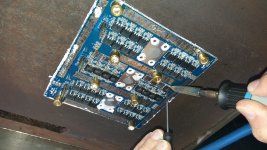
Me changing 48 mosfets on a hot plate
20201127_134128.jpg

The controller was repairable after that!?
So the fuse cut off the power before enough went into the board to burn it?

Looks like a win for fuses and you
💥🛡😅
 
dominik h said:
So called power pouch cells.
On the aside:
Gimmie a cell name. Chevy "Power pouch cells" cells are 10C, peak well over 2000A, 1mOh, and they are called " LGZ P2.7b" cell ( cell name)( as is on my bike) and are a heavy copper dense cell. I just keep my eyes open for things like this.

0.0005Ohm is low for a 20ah cell, I have a 60Ah cell that is that low but that is 3x the capacity. I was hoping for a cell name or number. Thankyou anyway for the info.
 
Back
Top