Custom Steel Commuter

Tetrault

10 mW
Joined
May 20, 2023
Messages
21
Location
Vernon, CT
Hello, all. Been reading and trying to learn things on the forum for a while but just joining now. I appreciate everyone’s knowledge here, thank you! Have gotten into commuting to work by Ebike. Have a two OEM bikes, but want something a little different. Something fast and stable that can reliably cruise near 30mph (48 kph) for my commute.

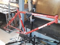
A great Ebike starts from a great bike, right? And what better place to find a great bike than people’s trash? This red one should be good.

It sports 26x2 inch tires, a 1 inch threaded fork, single piece crank, rim brakes, super solid rear dropouts. You know, top of the line. Sorry, no pic of it together as I was so excited to get started with this project…
20220121_194416.jpeg
 
Last edited:
I might've built this bike.... (different name, frame looks awfully familiar, though)
 
I might've built this bike.... (different name, frame looks awfully familiar, though)
Nice! Looks like you enjoyed it and that is was quite a while ago, relatively speaking.

My OEM bike is fairly "regular", which has lots of benefits. But, I want to try a direct drive rear hub motor instead of a geared one. Something with an integrated torque arm. I guess, from the selection on the grin site, that would be an M3540R.

It also would be nice to have some front suspension when at 30mph. Seems like a slack head angle makes sense too when moving fast. And a bit longer wheel base... I imagine rear suspension would be very nice too. With a large chain ring for pedaling at a very relaxed cadence when at speed.

Hmm...I think it's time to bring out the angle grinder...
 
Last edited:
You might look at my CrazyBike2 thread, in the later posts after I'd converted it to 2WD hubmotors; here's a post with some pics:

I didn't have rear suspension (just front) but you could easily build that into it if you felt like it. Here's a thread with various thoughts on that, but I've learned a LOT since then, and would probably do it differently than any of those (the bike itself changed since then, too)


I might end up with rear suspension in the successor, the Cloudwalker Cargo Bike.
 
Wow. I will go with something more conventional; a single pivot swing arm, aiming to keep the pivot at about the same point as where the top/tension side of the chain meets the chainring. This guys youtube videos have been amazingly informative:


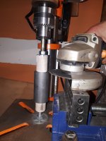
Anyway, here goes a suspension joint. Cut it down to size and "faced" it with an angle grinder while it was chucked up in a drill press. I can't say it worked all that well, but some hand filing afterward seemed to make it good enough. Will press some bronze flanged sleeve bushings into this, then slide a steel sleeve inside those and finish it off with a large bolt.

20220204_195316.jpg


Now....
7mmir5.jpg
 
Last edited:
Time for a rear swing arm!

Extending the wheel base will make the swing arm construction easier (no yoke or anything needed), allow for a large chainring, and hopefully add some stability at speed.

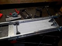
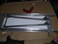
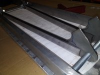
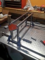
Taking ideas from the 10 year old fatbike DIY frame on here, I am using 1/2"x1" rectangular tube. Made a jig from some 1/4" aluminum plate and rectangular bar.

It will be a thru-axle rear, which I think made the jig easier. Shown here are the modular dropouts and 1/8" plate that will be the front of the swing arm.

20220218_121507.jpg


And some "chain stays".

20220226_202259.jpg

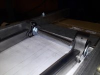
Closeups of the dropouts and front of "chainstays".

20220226_202343.jpg

20220226_202436.jpg
 
Last edited:
Great fab skills and attention to detail! Have you decided on the motor?
 
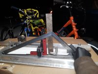
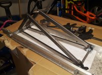
Had some trouble getting my pictures onto my computer. The swingarm is getting more triangular. I wish I had some more purpose-built clamps. But I don't wish enough to actually go buy any...

20220309_200757.jpg


20220310_200712.jpg
 
Last edited:
The swing arm above will replace the original rear triangle in order to allow for a rear suspension, stretch out the wheelbase for added stability at speed, fit a high-tooth-count chainring, and 2.5"+ wide tire (not sure yet). It is made of 1/2"x1"x0.065 steel tube.

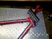
The bottom bracket shell, some seat tube, and possibly some downtube will be used from the original front triangle. Otherwise, it will act as a very convenient sacrificial jig. Getting the larger head tube located to allow for a 1-1/8" suspension fork as opposed to the original 1" rigid, also stretching out the front end and slacking out the head tube angle. Again for stability at speed, and I think during hard braking...not sure, but it seems if the front wheel is a little further forward relative to the rider, the bike would be less likely to endo.

20220316_205432.jpg
 
Last edited:
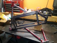
The plan is, if this actually turns out to be a rideable bike, to get some type of rectangular hard case battery. The front triangle will be used just to center the new rectangular box frame. Nothing exciting here, but getting the main box shape tacked up.

20220410_202759.jpg
 
Last edited:
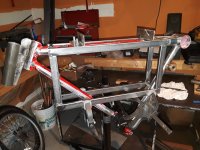
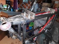
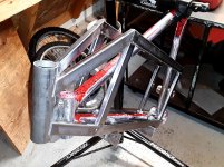
This probably doesn't make much sense to others yet, but here is the rectangular box being fit on to the "jig" (the old bike frame that will eventually be mostly cut away). The bike would be upside down here, with the down tube horizontal across the upper part of the picture.
20220420_192749.jpg
 
Last edited:
I like to see what you guys can come up with.👌 I've even been known to strike an arc or two.

But I don't understand what's going on with the steering tube. Is it just how you jiged it up, or is that how you plan on using it?
Yes, I realized posting that picture that things are getting strange looking. The red frame (along with the plate connecting the head tubes) will be mostly cut away, except for the bottom bracket shell and some of the seat tube. I only plan on building this one frame, so a frame jig seems way overkill. There are probably better ways to build than cutting up an old frame as a single-use jig, but this is seeming to allow me to proceed with minimal specialized tools. I did use some rectangular aluminum bar and plate for a simple rear swing arm jig, and a drill press, but most of the work is with an angle grinder. Whether it turns into a working bike is another story…
 
Last edited:
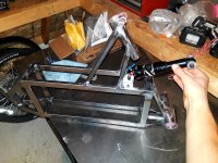
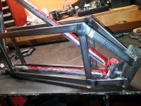
Tacking in the connections between the box and the bottom bracket shell. The ugly angle iron and bolts with spacers are fixturing to ensure the new rectangular frame box is lined up and centered along the old down tube (again, all the "red" tubing be cut away). If it is rectangular tube, then it is part of the new permanent frame, but if it is round, it is original and probably just being used as a jig.


20220420_192828.jpg
 
Last edited:
I'm not yet confident that the bike will be all that ridable, but I'm fairly certain that, with wheels, it will roll, and won't need to be carried :)

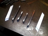
The 4 short sections of rectangular tubing to attach the new head tube* to the new box frame are notched. I ended up modeling the whole front of the frame in 3d, then, since these notched sections are rectangular tube, I could lay out each face of each of the 4 tubes flat in CAD, print them on paper, fold the paper, mark the tube and grind a relatively accurate notch. Not the most elegant method, but I have been able to make the notches using only an angle grinder and a small rotary tool (Dremel).

*For the head tube - As I read on this forum, you can run a 1-1/8" fork with an EC34/28.6 & EC34/30 headset using a standard 1.5" OD x 0.083" Wall x 1.334" ID Alloy Steel Round Tube...no need for specific bike frame tubing. Will just need a little material removal from the ID of the tube to press the headset in.

Pic shows 2 out of 4 of the folded paper templates.

20220504_205838.jpg
 
Last edited:
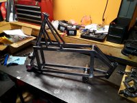
Rectangular tubing in the previous post is tacked into place, connecting the new head tube to the new frame box.
20220505_210151.jpg

And then some MIG welds, complete with plenty of fish eyes...

20220512_211626.jpg

As if those crater cracks didn't give it away, I now see that I should have moved all my scrap practice welds off the table first for a less "noob" look to these pictures :geek:. Either way, time to start saying goodbye to more of the old Savoy Casablanca frame. Hopefully bikes don't have feelings. Sorry Casablanca.

20220512_211645.jpg
 
Just the bottom bracket shell and the seat tube (and an inch or 2 of the down tube) left from the original frame. The top of the seat tube needs support because it will be separated from the bottom of the seat tube to make room for the rear shock. Used 1/2" square tube. Honed out the inside of the seat tube where the welds penetrated with some 6"L x 1/4" diameter shank "diamond" rotary bits from Amazon in a cordless drill. I didn't expect much diamond to be in them based on the price, and yeah...that took a while to get the seat post to fit back into the seat tube.

As for the welds in the bottom bracket shell, they can be left as-is because I will use a Black Ops BB American to Euro Adapter, so the weld penetrations won't be in the way of the actual bottom bracket. I'll see if I can "ream" the head tube with some gentile work with a Dremel sanding drum.

20220619_201310.jpg

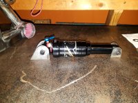
Made shock tabs, cut the middle of the seat tube away and am holding the shock in place to get an idea of the fit...
20220625_210249.jpg

20220625_210415.jpg
 
Back
Top