Cycle Analyst V3 interface to Arduino Nano33 IOT

Joined
Jan 19, 2022
Messages
81
I want to input a throttle signal from an Arduino Nano33 IOT to a CA_V3.
The Nano33 IOT is really nice; small form-factor, wifi, on-board IMU and has one analog output which I want to use as a throttle input to CA.
The analog output from the Nano is a 0-3.3v signal and I don't want to fry the little guy :)

Will I need to voltage shift the 0-3.3v signal to 5v?
I'm trying to keep the circuit as simple as possible...

With the throttle scaling features of the CA_V3, I'm pretty sure I can remap the 0-3.3v to the 0.85-4.25v signal required by the controller.

WIN_20230216_08_16_54_Pro.jpg
 
Last edited:
With the throttle scaling features of the CA_V3, I'm pretty sure I can remap the 0-3.3v to the 0.85-4.25v signal required by the controller.

Yes, that's all you have to do. No shifting or hardware scaling, etc. As long as the input into the CA does not exceed the 5v input of the CA throttle signal pin, referenced to the throttle ground pin, the CA settings for Throttle In will take care of that. Then use the Throttle out settings to scale the throttle output to match the device you're controlling with it .

Just curious: what are you going to have the Nano do?
 
Thanks for the confirmation. The CA continues to delight!
Have you noticed how just when you think you've got everything figured out...
I keep running into issues trying to get a 3.3v board to run an ebike, which is as you know is a 5v device :)
So I'm back-pedalling and going back to a 5v board despite it's limitations.
I don't want to discuss the project until I get a bit further along and see if I can get it to work. Cheers!
 
Actually an ebike is a multivoltage device, and some parts may indeed run on 3.3v (like MCUs inside controllers, etc), others on 5v, some on 10v, 12v, some on 15v, and some on whatever battery voltage the system uses (24, 36, 48, 52, 72, etc).

Even single devices like a common controller usually operate on at least three different voltages.

The Cycle Analyst uses at least three as well.

Knowing what you were trying to do would have helped us help you find a solution....not knowing at least what the goal is means we are working blind and cannot really help like we might be able to otherwise. We might be able to help you get it to work, rather than you having to struggle along completely on your own.
 
Knowing what you were trying to do would have helped us help you find a solution....not knowing at least what the goal is means we are working blind and cannot really help like we might be able to otherwise. We might be able to help you get it to work, rather than you having to struggle along completely on your own.
Thanks for the offer of help; too little of that going around :)
I made a simplified block diagram to show the goal of dual motor control.
The Master Motor is controlled by the throttle, PAS and ebrake (normal hookup).
Power from the battery to the master controller passes through the CA shunt.

The CA reads the shunt and transmits the current power to the Arduino via TTL/USB.
The Arduino calculates some percentage of this power and transmits a PWM signal to the CA throttle inlet.
The CA sends the slave throttle signal to the slave controller using ramp control.
1677171530374.jpeg
 
Last edited:
That's a pretty complicated setup to "just" run dual motors. Is there a specific reason the second motor has to be run so precisely? I would guess that the idea is for the second motor to only kick in once current on the first one rises above a certain amount? Note that the CA wouldn't be able to control the slave motor based on any of it's own current with it wired up this way, so this might introduce problems with limiting that slave system.

If so, I think the CA can be setup to do that on it's own, without using the arduino.... I haven't used that ability, but am pretty sure iyou can use a setup so that a certain amount of power is required before the motor kicks in, and get some proportional assistance from there. I think you would need to use the Torque sensor input to read the shunt (so a bit of analog hardware like opamps (or an MCU with appropriate analog I/O) to convert the tiny shunt voltage up to the range the TS input needs), so that it would provide motor power based on "human input power". Since the shunt input wouldn't be being used on the master system, it could then be used to monitor and limit the slave system if needed.

If that's not the reason, then more detail on the specifics of why / what it is doing may help inspire ideas on how to make it work.

FWIW, I have successfully used dual motors on CrazyBike2 and SB Cruiser even with different diameter wheels and different motors entirely, even different controllers, and a single throttle for both (or separate throttles).

The systems were not perfectly setup, but they worked, and did what I needed them to. ;) SB Cruiser still does, though I always have ideas (let's not get overconfident and call them "plans" :lol: ) to improve and experiment with it.

One improvement would be a steering-dependent power control, so that the further I turn the handlebars, the more power is applied to the outside wheel and the less to the inside, to help me turn sharper turns on the trike. It would be a very simple approach, essentially just an old throttle mounted to the steerer so it's turned by the frame (or vice-versa) and that voltage output monitored by a Nano that then takes the CA's throttle output and splits it into two independent throttle signals, proportionally altering them based on the steerer input.
 
Having the arduino in the loop brings a couple of benefits and I do understand that the cycle analyst will not see the power to the slave.
Not shown in the simplified block diagram is the LSM303 IMU which will inform the arduino of the incline as well as if the bike is in a turn.

With information from the IMU, the arduino can intelligently proportion the power between the front and rear motors.
It will apply a higher percentage of power to the front during ascents, decrease power to the front when turning and preferential power the most efficient motor on the flats.

One of the reasons for the precise control of the slave is for winter riding (in Canada).
Every day this winter I rode the bike over a cake of snow/ice and noticed the unpowered front wheel had a tendency to turn downward in turns;
when the front turns down, so does the rest of the bike :)
Applying the correct amount of power to the front under these conditions needs to be done with careful precision.
 
Traction control is certainly a good reason for precision--crashes are no fun especially if you slide under a moving car.... :(

Once the system is working in the front, are you considering also implementing a form of it in the rear, or will that remain under manual control?
 
At the beginning of the winter (on my birthday) I fell three times on the ice in one ride.
The last fall knocked something out of kilter (on the bike that is). My battery drained super fast and left me pushing the last 5 km.
After that I decided for health and longevity I HAD to quit falling if I was going to last the winter.
Luckily, no falls since but it's like riding on a knife-edge :)

I'm actually practicing with this setup on the rear right now as no motor installed on the front yet due to the stock fork.
I'm searching and searching for a 26x4 non-suspension, chrome-moly replacement fork with a 350mm steer tube (1-1/8" non-tapered), disk brake ready.
It's proving to be a very difficult thing to find...
 
Do you use studded tires? If you are on ice all the time that might help (but not if you have to transition to non-iced surfaces).

What is it about the stock fork that is preventing you using the motor on it? Some things can be worked around easily enough, some take more DIY.

If you can't find a non-tapered steerer, can you change your headset out to use a tapered one? Or is the headtube too narrow at the bottom?

Back to the original topic--Given the connections, I don't see a reason the 3v3 setup wouldn't work, though a 5v system may simplify some things. (you'll probably want to use a separate DC-DC off your battery, or a separate battery entirely, to run the Nano and it's sensor(s), though, rather than powering them from the CA or the controller, if they use more than a few mA). What specific issues have you run into with 3v3 vs 5v?


On the diagram, the PWM output of the MCU is going to need to be filtered (RC, lowpass) prior to reaching the CA's throttle input, to provide a steady voltage for the CA to read. If it's an actual analog signal output as noted in the OP, then no filter is needed.

I am not sure why you have the relay between the Nano and the CA? Simply turning the nano's output to zero would disable the output. Alternately you can use the signal from the nano that would have driven the relay to control the CA's ebrake input, which can then be setup to disable throttle output when engaged. Saves you a relay and some power.
I run Terrene Cake Eaters (normal studs) and have had to change them out a couple times with the stock tires when the roads thawed (La Nina winter).
The only other necessary gear for winter riding up here is a pair of Bar Mitts to keep the hands toasty.

The stock forks are the original suspension fork that have 10,000+ km on them. Also there's some posts on EBR forum that warn against installing a hub motor on a suspension fork. The advice was to use non-suspension steel, not aluminum, because steel will bend before snapping.

I'm not sure about changing the headset; it's something I need to look into. The good forks these days all seem to be tapered so this mod would open up a lot of new possibilities :)

I've already given up on the 3.3v board and reverted to a 5v. It has a bigger footprint but it's working good and has a lot more program memory. I'm using a 48v/12v DC converter, originally for my winter headlight, but it has plenty of capacity to power the arduino. From the 12v, I also power a tiny 5v power supply for the sensors just like you mentioned. One specific potential problem I ran into with the 3.3v board was interfacing the TTL input from the Cycle Analyst.

Since the PWM requires filtering, I'll change the signal to a true analog using an DAC chip (MCP4725). It talks to the arduino through I2C comms and serves up a 0-5v signal on the output.

You're right about the relay. It's in the project box from when I was doing some some throttle switching but now it's not needed.

Thanks for all the comments and guidance, I really appreciate it.
 
Last edited:
I'm working on the cycle analyst to ardino ttl connection to read the master motor power and trying to figure out the best way to make the connections. I have a CA TTL to USB cable that has the proper plug for the CA. I think I have two options and I'm not sure which way to go.

The simplest would be to cut the TTL>USB cable and use two wires inside (Tx,Gnd); the cable was a little long anyway :) It is also the programming cable so I'd have to order a new one; no biggie.

The second method would be to open the CA and solder a wire onto the Tx pad (don't need Rx). As far as the gnd connection, there are several on the various CA sensor inputs and I'd just make a solder connection to one of them.

With the 5v board, a direct connection between the CA Tx and the Arduino serial Rx should not be a problem. Am I missing anything here?
 
Not really...but there is another option:

If you aren't using the USB to connect to the Nano and only need the serial data directly, you can use an old headphone or computer-speaker cable (TRS 3.5mm stereo). IIRC the white wire on those is Tip (left), red is Ring (right), and the shield/braid is Sleeve (ground).

Per the Grin site the ring is TX on the CA, so you'd wire the red wire (or whatever is on ring) to the Nano's RX, and the shield (sleeve) to Nano ground.
CA3_Pinouts_2017[1].jpg

Then you can easily unplug the Nano from the CA and still use the CA's serial port for programming, etc.
 
Last edited:
I checked a set of headphones, ear buds and audio extension cable and they all have three rings on the plug.
Inside the audio extension was two wires and shield. Great.

Then I checked the CA programming cable and it has four rings on the plug and sure enough it has 3 wires and shield inside;
continuity checks showed the order from the tip is white, green, red and shield.

Just when I thought I had everything figured out :)

I have a hunch on what's going on. Somewhere I read that a GPS can be connected through the same cable. I searched for a wiring diagram but couldn't find one; I wanted to see where the GPS would get it's power. But now I think I know. So the fourth wire in the cable, probably the red one, is 5v+. The shield is the gnd of course and the White and Green are transmit/receive; not sure right now which is which;
this is just a hunch.

So it got me thinking, a GPS would probably be a good idea and could be powered off the red/shield and transmit to the CA Rx and I could hook up the arduino to the Tx of the CA sharing the same grd and Viola, bi-directional communication for three devices all on the same cable. Wouldn't that be a hoot?
 
Last edited:
Only three wires are used on the CA's TRS 3.5" female serial connector, per the wiring diagram I linked and posted before--RX, TX, Ground. No power is available on that connector per Grin's documentation. (I haven't measured mine, but the single (broken) CA I happened to have in a drawer here with this connector only has three wires from it soldered to the CA board. (I didn't open the sleeving to see if there are more than three wires inside the sleeve).

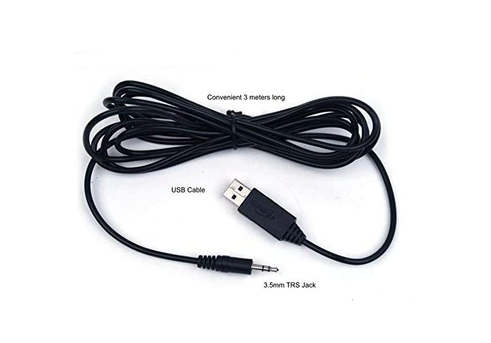
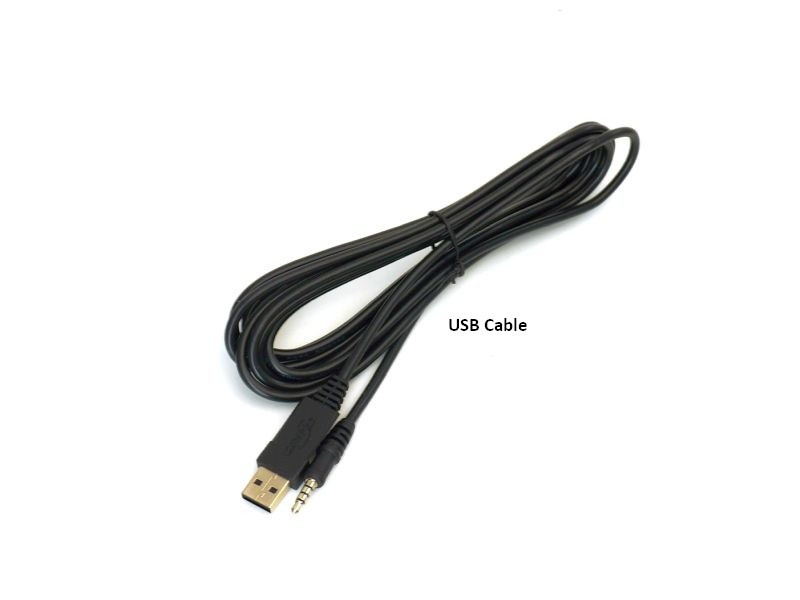
The Grin Tech USB-serial cables I have here are both just TRS, so one Tip, one Ring, and one Sleeve. Neither are TRRS (Tip Ring Ring Sleeve), so a standard TRS headphone plug would work just fine.

Note that the rings are not the plastic separators between metal, but the actual metal itself. The sleeve is the one that starts just beyond the plastic base of the plug where the wiring goes in. The ring(s) is (are) the metal bands between the sleeve and the tip. The tip is...well, the tip. ;)

You can open your CA to verify the wiring, in case yours is different from the Grin documentation.

TRRS plugs/jacks *are* used on some devices intended for phones and tablets, for instance, as they also have a microphone on the headset, and/or button controls, that use the second ring for their signals.

They may also be used on some serial port devices using the 3.5" jack of this type, probably with 5v power on the second ring, but it is probably device-specific, so the cable would probably have to come with it or be wired to match it..

Note that on a single serial port of this type, you cannot connect more than one device's TX to any other device's RX line. You can hook up several RX lines to one TX line, up to the point that signal degradation occurs due to too much load on the TX line.

So you can't actualy have bidirectional communication between more than a pair of devices on such a serial bus.

There are busses that can do this, like I2C, SPI, etc, but the type used on the CA (a variant of "RS232") can't do it.

The Cycle Analogger has a GPS option, but the GPS does not communicate outside the Analogger box (no connection to the serial port at all)--it is just read by the Analogger MCU to log the GPS data onto the memory card along with the incoming serial data from the CA (over that TRS jack noted above). I cant' remember where the Analogger gets it's power, either an internal coin battery or from the CA's "headlight jack" that carries battery power on it, most likely. Grin's page for the Analogger should have that info if you need it.
 
As you can see in the photo, the plug has 4 contacts and inside you can see the three wires plus grd (covered in black heatshrink).
(You're actually seeing the four dupont jumpers I soldered to wires inside the TTL cable.)
I plugged into the TTL jack on the CA and measured a rock steady 5v between the green wire (second from the tip) and ground. The red/white must be Tx/Rx.
I got to thinking and remembered I had ordered this from Golden Motor when I had purchased a hub motor from them.
So they have a slightly different V3_CA????>

as far as the GPS, this is a quote from the Grin website:

The Experimental category currently includes two branches that can be of interest to users doing more advanced vehicle analysis.

The 3.13X1G code allows the CA to read and display data from a NMEA output GPS sensor, including position, elevation, heading, time etc. Normally this would be achieved with a simple modification to the GPS Analogger device by connecting the GPS's output to the CA's serial input line via the existing TRS cable. The data output stream saved by the analogger then includes a single file with synchronized position information which simplifies uploading and viewing on our trip analyzer web application.
1677295623066.jpeg
 
Last edited:
I'd never seen that experimental GPS stuff; only knew about the Analogger version. :oops:

I'm not sure why the CA (and USB-serial cable) you've got is wired differently than the Grin docs or the one(s?) I have here--it could be a GM specific thing for whatever reason, or a change from Grin that isn't documented yet (pretty sure all the hardware I have is at least 3-4 years old, some much older, as it all still has JSTs instead of the WP connectors).

But given the difference, I have no idea which wires would be whicn functions, or which positions on the TRRS plug are which. This you can determine easily enough with a multimeter set to continuity, diode test, or 200ohms, and then with the CA dicsonnected from all power, and no power to the serial cable, you plug in the serial cable to the CA and open up the CA and measure each pad on the CA board that goes to that cable and each wire at the other end of that cable, and note down which pads go to which wire colors. Then you can correlate those to which position on the TRRS they are as well if you need that info too, but the wire colors should be sufficient for this purppse.
 
OK. So I made the ground connection between CA and the arduino.
Then I tried each of the three wires in the Rx terminal of the ardino.
It's always the last one you try, which in this case was the green wire.
I'm getting the CA logging stream into the Arduino so all is good!
 
Just a followup, I surfed over to Golden Motors and found they sell two different CA programming cables.

One has a TRS plug and is for CA's only:

The other cable has TRRS plug and is said to be compatible with CA, phaserunner and satiator:

Mystery solved.
 
I'm back to using the nano33 iot as in the OP for the DAC0 analog output (for the throttle). One nano33 is running the front motor throttle and one the rear. Since I need to read the 5v CA data log, I introduced the raspberry pi into the design. The pi actually handles 4 serial connections; CA data stream, two nanos and a neo6m GPS. (The nanos also carry on a serial communication between themselves to coordinate their motors.)

I decided on the solar firmware for the CA because it accepts a solar shunt on the auxA. This way I can have power reading on both motors.
For this firmware, solar shunt reading becomes part of the CA data stream.

Here's the block diagram and it's pretty much an as-built for what I've put together so far..
(The front motor arrived and installation is almost complete.)
I dropped the neocolonialism master/slave terminology and just use front/rear now. The front has actually become the "master" unit because it's power is calculated based on accelerometer input (incline and roll). It's calculated power is sent to its throttle, subtracted from the total power required and transmitted to the rear nano over their private comm link.

Independent of the CA, I need an instantaneous, accurate front wheel rpm (traction control) and was thinking about using a 12-magnet pas ring and pas sensor.
Anyone know of a good Arduino PAS sketch and schematic?

1678622581258.png
 
Independent of the CA, I need an instantaneous, accurate front wheel rpm (traction control) and was thinking about using a 12-magnet pas ring and pas sensor.
Something to consider for total reaction time:

How low an RPM does it need to be "instantaneous" at? With a 12magnet PAS ring and sensor (at the hub/axle-dropout interface, presumably), it will take something like 1/12 of the wheel speed to get just one response from the sensor, then whatever time it takes to calculate the RPM change from that plus the last reponse, vs the previous time between responses.

More magnets means faster response at lower RPM (though there is now more data to process).

Reaction time also includes whatever time it takes to send data back and forth between the two motor nanos and have them begin to change controller output, along with the time it takes the CA to read current and send it back out the serial port and the nanos to read and process that. (everything has a latency, and some of them can be pretty large--for instance, some cheap controllers can take as long as half a second to respond to a brake lever input! :shock: ).
 
Something to consider for total reaction time:

How low an RPM does it need to be "instantaneous" at? With a 12magnet PAS ring and sensor (at the hub/axle-dropout interface, presumably), it will take something like 1/12 of the wheel speed to get just one response from the sensor, then whatever time it takes to calculate the RPM change from that plus the last response, vs the previous time between responses.

More magnets means faster response at lower RPM (though there is now more data to process).

Reaction time also includes whatever time it takes to send data back and forth between the two motor nanos and have them begin to change controller output, along with the time it takes the CA to read current and send it back out the serial port and the nanos to read and process that. (everything has a latency, and some of them can be pretty large--for instance, some cheap controllers can take as long as half a second to respond to a brake lever input! :shock: ).

Thanks for the guidance, amberwolf :)
The 12-magnet solution is pretty slow when I need it the most at low speeds; but remember when the tire breaks free it's gonna turn a lot faster :)

At 30 mph, a 24-magnet ring would produce a pulse every 7 millis; my front wheel sketch is running at 11 millis ( a lot of IMU data smoothing.) so maybe with interrupts I can catch all the pules? (With the 12-magnet ring I don't even need to use interrupts.)

Thinking outside the box here, two rings would be better than one; 12-magnet for high wheel speed and 24-mag for low speed with a hall sensor for each.
( Physically, it would just be one ring with two magnet circles). The program would switch between the two sensors depending upon the millis between the pulses; best of both worlds without a lot of complication.

I'm minimizing latency head-on by having the traction control run on the front wheel nano which reads it's built-in IMU and analog outputs directly to the CA throttle input. All corrections that need super fast response are carried out within the nano itself without the round-trip time to the rear nano or the CA data log retrieval; so the response will be about as fast as I can make it except for latency in the CA throttle read/write. During a traction "event", I probably need to bypass the CA and take the throttle output directly to the controller because the CA will be doing a lot of throttle profiling to smooth out power application to the front wheel.

I think I'm also going to need to know the rotation angle of the front fork relative to the frame; it would help determine the power to deliver to the front end during "events". All my slips seem to be at higher fork angles...
 
Last edited:
The last part is pretty common, since your'e dealing with inertia forcing forward motion at a different angle than the tire/contact patch is moving at.

With the SB Cruiser trike, I don't typically lose traction on the unpowered front wheel during braking except when I am turning at a fairly sharp angle. But when turning into my driveway at home, even at say, 5MPH, I'll skid a couple of feet in the same direction I was going at the instant braking starts if I apply the brakes just a *touch* too hard.


You'll have to measure the CA latency to see if it will be a problem or not (easy enough to do with an oscilloscope, and something to drive the throttle input over a range automatically, like a triangle or sawtooth waveform.
 
Relay wiring can get a bit confusing 😰 so I made myself a sketch before I started on the connections.
(The traction relay bypasses the CA during an event so the nano has full control.
Usually it just passes the CA output to the controller.)
dual motor throttle control.png
and IRL, this is what it looks like:
dual motor throttle photo.jpg
 
Back
Top