
beemac
10 kW
I posted this here rather than in the general tsdz2 threads as they are behemoths - and the question is about general electronics than the tsdz2 really...
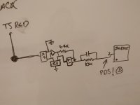
I'm trying to work out the circuit that is used to read the torque sensor - so I can replicate it and interface to an nrf52840 (or any other microcontroller).
I've traced a pcb I depotted - and I believe the circuit is as the image shows. But I'm not really sure what the components KF or G1 are - I *think* the component marked KF is a diode - something like this https://www.s-manuals.com/pdf/datasheet/b/z/bzx84_series_r6_nxp.pdf and the G1 is a transistor - something like this https://assets.nexperia.com/documents/data-sheet/PMBT5551.pdf but they are just ill-informed guesses based on googling and my basic electronic knowledge.
Image shows the red connection to the torque sensor - from what I can tell black is just connected to ground.
Unfortunately the pcb i'm tracing has a broken power stage - so I can't power it up to see where any voltages are input to the circuit. My guess is there's at least a 5v connection missing somewhere.
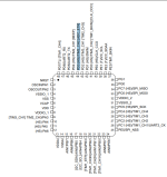
The circuit connects back to an ADC pin on the STM8 controller - and that maps to PD3 which is the right pin - so it's def the torque sensor circuit.
Can anyone shed any light on what the circuit is doing and clarify any of the components by any chance? :thumb:
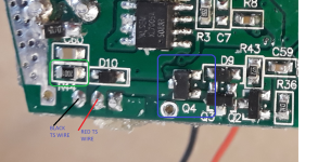
I've added a pic of the pcb - ignore the blue/green rings. KF/G1 packages are SOT23 I believe. Or are they - i've just noticed KF is fatter - but I can't find my calipers to confirm the sizes.
Q4 = KF
Q3/Q2 = G1
I'm trying to work out the circuit that is used to read the torque sensor - so I can replicate it and interface to an nrf52840 (or any other microcontroller).
I've traced a pcb I depotted - and I believe the circuit is as the image shows. But I'm not really sure what the components KF or G1 are - I *think* the component marked KF is a diode - something like this https://www.s-manuals.com/pdf/datasheet/b/z/bzx84_series_r6_nxp.pdf and the G1 is a transistor - something like this https://assets.nexperia.com/documents/data-sheet/PMBT5551.pdf but they are just ill-informed guesses based on googling and my basic electronic knowledge.
Image shows the red connection to the torque sensor - from what I can tell black is just connected to ground.
Unfortunately the pcb i'm tracing has a broken power stage - so I can't power it up to see where any voltages are input to the circuit. My guess is there's at least a 5v connection missing somewhere.
The circuit connects back to an ADC pin on the STM8 controller - and that maps to PD3 which is the right pin - so it's def the torque sensor circuit.
Can anyone shed any light on what the circuit is doing and clarify any of the components by any chance? :thumb:
I've added a pic of the pcb - ignore the blue/green rings. KF/G1 packages are SOT23 I believe. Or are they - i've just noticed KF is fatter - but I can't find my calipers to confirm the sizes.
Q4 = KF
Q3/Q2 = G1


")


