
Alan B
100 GW
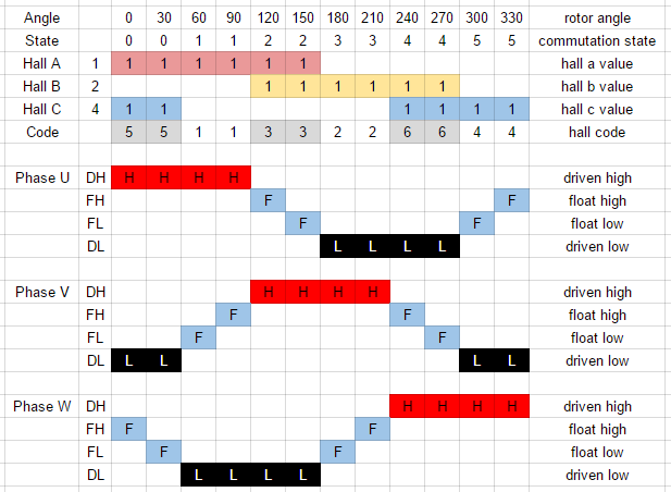
I need to have my own documentation for halls and phases, so for now I made it a spreadsheet. Perhaps I'll make it a drawing later, but right now I don't have a convenient drawing tool to do it with, and there is a lot of spreadsheet style data that needs to be there anyway. I relabelled the phases to U,V,W again, I've gone back and forth a couple of times on that.
One thing I did is to divide the chart into 30 degree intervals to expose the sensorless transition event. So above is a first draft. The "Float High, Float Low terminology is with respect to the midpoint voltage, so you can see at 30, 90, 150, 210, 270, 330 there is a floating transition between high and low (in one direction or the other). These are the sensorless "zero" (really midpoint) crossings that start the timer for the next commutation event that occurs 30 degrees later.
I'm working on an algorithm that can watch both the hall events and the sensorless transition events and use whichever is the best quality with a preference toward sensorless events if both are good. In normal operation it would start from stopped with hall sensors and then smoothly transition to sensorless when the signal is good enough. So if the halls fail it would become pedal start (at least for direct drive motors). In some cases, perhaps under heavy throttle, load, vibration or sagging battery the sensorless data may become noisy and it would just seamlessly switch to use the hall sensors, and then transition back when the sensorless noise cleared up. We'll have some logging so we can see what is happening later. Perhaps an LED for Sensored mode? If that flashes while moving there's something noising up the sensorless data.
Note that for a gearmotor pedal first won't work, but I'm not going to try to fix that now, that can always be an exercise for the reader.
")
Another feature I'm thinking of incorporating from the start is a hall sequence check, I don't think the common controllers have this based on how they operate when the hall wiring is incorrect. The sequencer will essentially enforce the correct order of the hall states, and if they occur in the wrong order it will declare an error, shutdown the outputs and require a drop of the throttle to clear it. This lets you know that the halls are not wired properly, or there is noise or a loose connection or a failing hall sensor. This will also prevent getting the wrong hall sequence when setting up the wiring. Rather than the motor continue to run improperly, it will try and quit, and retry each time the throttle is lowered/raised again. So you'll know the halls are not right. We can always take it out if it is too annoying, but it seems to me that getting the system right and solid is better than having it appear to work when it is not quite right. If it quits when out riding then there is a problem. I will put some filtering so a single bad reading won't count but several in a row will trip it.
A similar timeout on the motor not turning, or going backwards would be good also. Try to catch those things that heat up the controller and motor and trip them quickly. With a simple throttle reset, not a power cycle.
The current sensing shunt is located between the capacitor bank and the FETs, instead of the usual location between the battery and bulk caps. The link caps are on the FETs as they should be, but putting the shunt after the bulk caps allows it to see the current peaks instead of just reading averages and being very delayed when there is a fault. There's a fast comparator and DAC in this CPU to set adjustable thresholds for quickly tripping off the FETs (in hardware, bypassing the CPU) if the current spikes. The goal here is to protect the controller from overcurrent faults. This CPU again shows its credentials for motor control.
It would be nice to automatically determine the hall wiring, but I'm not planning to start there. That can be an improvement for later on. That's a nice feature, but not really necessary. KISS principle.
edit - updated the spreadsheet with some color, expanded some features