DIY Sensored BLDC ESC - Assembly Thread

S.B.D

100 mW
Joined
Dec 29, 2011
Messages
41
Hi,

After the DIY brushed ESC success, my friend and I took the challenge and designed a sensored BLDC ESC.
After reading a lot of material (thanks to ES members!) we started looking for off the shelf components to implement it.
All components where taken from Digikey.
I took on the hardware design and my friend the firmware and PC interface.
After finishing the schematics, PCB editing took around 3 weeks and the gerber files took an e-mail ride to China for fabrication.
The PCB panel hosts 10 ESCs. It is a 4 layer design with 1oz copper on the outer layers and 3oz copper in the inner layers.
Most components are SMT, resistors and ceramic caps are 0805. The design is based on 12 x N-Ch MOSFETs (75V, 7.5mOhm).
3 National Semiconductor half bridge MOSFET driver will drive the MOSFET gates
A PIC18 micro will manage the ESC. This is the same MCU used in our DIY brushed ESC.
This small PIC has built in USB that we use for firmware update and parameter updates. A single PWM will drive the high side FETs using the PIC's pulse steering mode.
Pulse steering lets you use the same PWM on multiple PIC IO pins. The low side FETs will be driven at 100 duty cycle with a general purpose IO.
An external analog MUX gives the ability to use only 4 IO pins to measure 5 different parameters and even control an LED :mrgreen: :
- Pack Voltage
- Motor Current
- Throttle voltage
- Switch position (mode select)
- ESC temperature
- Toggle a latched LED

Motor current is measured using the same design as in the brushed ESC. An external op amp used to amplify the current on a 1 milliOhm shunt by 20.
The op amp is also used as a second order sallen-key low pass to filter out the PWM switching. This will reduce stress on the MCU as it will have to average fewer samples.
Low pass is targeted at around 1kHz.

The hall sensors are connected to 3 interrupt on change pins.
Power to the circuit is regulated by a high voltage regulator (125V input) down to 12V for the MOSFET driver, another regulator connected to the 12V rail sources the 5V needed for the circuit's logic.

I received the PCB and components a couple of weeks ago but found the time to start assembly only today.
Assembly strategy - places ICs first, than SMT resistors & SMT Caps... After this I will place all the top side through hole components and than all TO-220 components on the bottom side.
I will build 2 ESCs for now so I'll have something to compare with when nasty smoke appears :D .

The firmware is written in C and uses components form the brushed ESC code (current measurement, throttle reading, temperature reading, EEPROM writing...).
We started writing the low level routines on the PIC's evaluation board, but waited for the boards to write the control state machine.

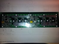
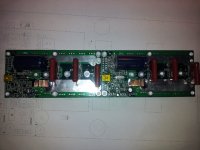
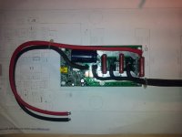
I attached some pictures of the PCB panel, IC placement & SMT resistor and caps.
That all for today... will post more as I progress.
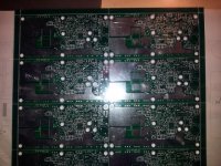
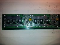
BLDC PCB.jpg

BLDC ICs.jpg

BLDC Res&Caps.jpg

S.B.D
 
Hi,

Found little time today to continue the board assembly. Finished soldering all the Through hole capacitors and 5W 1mOhm shunt resistor.
Next up will be to add the 2 voltage regulators and 12 MOSFETs.

BLDC_TH.jpg

S.B.D
 
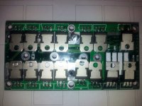
Today, I placed all the TO220 components on the PCB bottom side.
12 x 75V 7.5mOhm MOSFETs
1 x high input voltage regulator
1 x voltage regulator
1 x reverse polarity diode

Next up, wire the board and connect the PCB to a heat sink using a thermal pad.

BLDC_TO220.jpg

S.B.D
 
I think it's VERY cool you're making your own controller, but I hope you are aware that FET you picked is a serious dog of a component.
 
liveforphysics said:
I think it's VERY cool you're making your own controller, but I hope you are aware that FET you picked is a serious dog of a component.
I didn't see where the OP identified the FET. Was it the package that led to your dog comment?
 
Hi,
The MOSFETs I assembled are +STP140NF7​5;16 from ST Microelectronics. Same ones I used in the brushed ESC.

S.B.D
 
Hi,

Managed to find a decent amount of time to continue working on the BLDC controller.
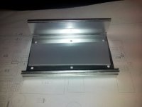
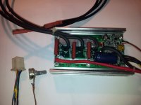
I found an burned battery charger in my junk and used its aluminum case as the ESC enclosure - perfect fit!
Drilled the 6 mounting holes and added the FujiPoly thermal pad.

For now I soldered the battery wires, motor wires and a servo lead connected to a 10k pot for the throttle.
Later on I will add the on/off switch, mode switch and brake lever.

I had a problem programming the MCU - turned out to be a resistor value problem. Instead of a 4.7 ohm series resistor on the MCU's VCC I placed a 10k resistor...voltage drooped to 1.5V.
Several hours where spent on moving code from the brushed controller to the new brushless project (current limiting, throttle reading, temperature reading, voltage reading ...).

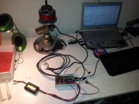
First step was to connect the motor's halls to the ESC to check the commutation sequence. Turned the motor by hand and used the scope to see if the pwm was routed to the correct FETs.
At this point throttle control currently works very bad and the captured signal fluctuates a lot, I think this has to do with the analog mux treatment in the code... will check this tonight.

Connected the motor phase wires and throttled up....motor started moving pretty smooth but with a high no load current of about 3A.
Crossed two phase wires and throttled up again.... no load current in now 4A, motor jerking around.
Another iteration of the phase wires fixed the problem, motor runs smoothly at 0.75A no load current.

At 1:30AM I decided to call it a day, falling asleep without smoke seemed the nicer way.
Next up, fix the throttle capture problem and have a better look with the scope on the switching nodes and MOSFET drive.

Box.jpg

Wiring.jpg

Inside Box.jpg

Setup.jpg

S.B.D
 
In case you find any problem of heating,
remember the IRFB3077 mosfet can be a very good friend :wink:
Especially if you want to target the 60A, 60V and 3600W low-power user of ES :mrgreen:
Very nice design!
have fun!
 
Liveforphysics sent me a PM with this exact part number.
Apparently I did not go over enough ES threads...

Thanks for the tip. I will source these next order from Digikey.

S.B.D
 
Excellent project! Could this turn into the EV world's Megasquirt equivalent?

Sorry if I missed it, but what are the ratings of this controller? Would it be capable of performing regenerative braking?

Chris
 
Well, last night we continued working on the BLDC controller.
The throttle bug is fixed and we now have a great working throttle with programmable endpoints.
Next we looked at some scenarios where we saw jerking, mainly in very low RPM or "very" high RPM.

I decided to try 2 things...the bad thing I changed them both at the same time so I don't know which fixed the problem.
For very low RPM I decided to try increasing the bootstrap capacitor from 0.1uF to 1uF.
My thought was that the very low duty cycle (short charge time for the bootstrap cap) along with the the long time between charges may be the problem.
I could not sync the scope to see the problem properly.
Second change was to increase the capacitors on the hall sensor lines to get better low pass filtering. Put 22nF instead of the original 100pF.

Both changes made the motor run great! from very low RPM to max RPM.

next bug fixed was a single motor jerk at power up. This was a code bug that did not init the PWM module correctly.

We then moved on to a 36V pack.. all running smoothly!

Then came the 48V pack. Battery connected to ESC, Throttle up....and smoke... The 1000uF cap flashed :( .
The cap's positive lead was burned in the middle and fused.

That was the end of a great night.

In the autopsy I found that the 1000uF/63V was dead, the 10uF/100V LDO input cap was puffed, 1 low side FET shorted and also a very strange thing...a short circuit between VBATT and one of the high side FET gate.

I have a feeling that this short was there from the beginning but when we moved to a 48V pack the Vgs was way over the max rating.

lessons learned - when testing or developing power electronics use a current limited power supply or at least a fused battery.

Here is a link to a movie of us in the middle of debugging.
http://www.youtube.com/watch?v=yrnk0lvhkCw

I'll fix the board and continue updating.


S.B.D
 
Shit happenz :mrgreen:
Definitely for testing a current limited supply is better than a badass low R LiPO :oops:
I must say your design with USB debugging mode for the controller is very sweet!
Any hardcore user would be more than happy to be able to tweak and log his/her controller
in real time. Keywin programming is fine, but something more complete would be great!
keep us posted!
have fun and no more smoke!
 
Subscribed!

Pretty cool! What ratings are you shooting for?

Jay
 
Hi,
Since this is our first attempt at a BLDC controller we would like to reach around 1.5kW @ 48V.
Current goal is to understand why the input cap failed @ 44V input - no load... :(
The design is very simple and does not implement synchronous rectification, so it will not be efficient enough for very high currents.
IRFB3077 FETs will surly help and I'll get those on my next Digikey order.

S.B.D
 
S.B.D said:
Current goal is to understand why the input cap failed @ 44V input - no load... :(
IRFB3077 FETs will surly help and I'll get those on my next Digikey order.

For the cap: it could have been a shame quality component from china? or you could have had
a problem with commutation spikes coming back to the input cap. :idea:

This bring the attention to the mosfet: if they were low quality parts, possibly ESD demaged,
some wrong commutation or one mosfet not going totally off, could have led to the exploding behaviour you got ... :arrow:

have fun and good luck!
 
Last night was a smokeless night. After fixing the controller we went on to use a current limited power supply and later on a fused 48V pack.
After an initial power up with the power supply - limited to 30V we came back to the dreadful 48 pack. This time a 5A fuse was added :)

Everything worked properly this time using the same type of components that failed last time. This strengthens my theory that the short circuit I found from Vbatt+ to a high side FET gate lead to the 4th of July effect.
One change I make was to increase all gate series resistors from 10 Ohm to 100 Ohm in order to decrease dI/dT stress on the FETs.

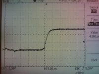
Here are some scope PICs I took:

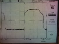
Low side FET turn on time:
Low Side Gate turn-on time.jpg

High side FET gate (Ground referenced)
High Side Gate GND reference.jpg

Phase Voltage (Ground referenced)


Also some Vids of the setup in work:
http://www.youtube.com/watch?v=yNC_Ar12cfw

http://www.youtube.com/watch?v=cNmBVIWDO1Q


A Lot of work ahead...

S.B.D
 
Hi,
Last night we connected the ESC to my friend's home built 6S LiPo Scooter. This scooter uses an RC outrunner Brushless motor fitted with external halls.
The controller worked great! The throttle endpoint adjustment via the USB interface was very simple.
First we programmed the current limit to 10A and started riding. ESC only slightly warm.
Next we stepped up the current limit to 30A. This heated up the ESC to very hot temperatures....need to implement the temperature measurement with the on board NTC thermistor....

It was very nice to finish a day without any damage.

Next up:
--Lower the gate series resistors from 100 Ohm to about 10 Ohm - would like to get your comments on this issue.
--Move the ESC from the scooter to test on a bike.
--Order a stick of IRFB3077.

S.B.D
 
S.B.D said:
need to implement the temperature measurement with the on board NTC thermistor....

I'm not too fond of thermistors as temperature sensors... non-linearities, and all that. And to drive/sense them properly takes circuitry. For most stuff, I like the LM34 style sensors. (note: in the TO92 package, the main source of heat input to the die is via the leads. I leave them long and pot them onto the surface to be measured with thermal epoxy. But then, I'm a temperature snob. I've built temp sensors with micro-degree resolution and milli-degree accuracy.
 
Hi Tex,

Thanks for the note.
I have experience with temperature measurements with various kind of probes (ntc, pt100, thermocouple 2,3,4 wire) and aware of the problems with NTCs.
I plan to port the code I used for a different project to read the same NTC. It uses a look up table every 5 degrees (copied from the datasheet) and than linear approximation between two points.
Even without calibration I don't see a problem to reach +/- 2 deg accuracy , much more than I need.

Milli degree...never done that... maximum accuracy I dealt with was about 0.2 Deg.

S.B.D
 
Yesterday we assembled the ESC on an e-bike with a rear hub motor.
The change to 5 Ohm gate resistors dropped the ESC temperature and even @ 40A it became only slightly warm.

We did find a few bugs:
- When the bike was moved in reverse the ESC acted as a brake. This is because of the current commutation state machine that leaves one bottom MOSFET "ON" according to the halls state.
Turning off all the bottom MOSFETs at minimum throttle should solve this.
- Starting the ride on a sharp incline cogged the motor. Need to figure out if this is due to an MCU reset, noise on hall signals.... Your comments on this will help a lot.
- Top speed seemed to be lower than that of an off the shelf 30A ESC, this needs to be verified empirically.

Things to do:
- Move to even lower gate resistance. Is 1.5 Ohm a good choice?
- Add a lead/lag phase compensation loop.
- Shorten hall & phase wires. Currently they are about 60cm !
- Move to IFRB3077 MOSFETs - ordered.
- Keep having smokeless fun..

S.B.D
 
Back
Top