Doing the Math

Kingfish said:
Hiya Biff

Copper fill
I ran several simulations that did show marked improvement when the windings were filled to their maximum, however I am not convinced that the stator could be constructed having any rigidity without some sort of support. For that I allowed 2mm between the windings to provide ribbing, and likely a perimeter band as well. I haven’t decided if the sides facing the magnets will have a thin facing sheet as well: Everything depends upon flatness, and maintaining that flatness during some very high lateral forces. Not having built one before I tend to err on the conservative. The losses are visibly noted in the graphs below.
Yep, stiffness is a big issue with the CSIRO motor. Once those winings get warm, the stator turns to jelly, bends, makes contact with the rotor (there is a 2mm airgap beween the stator and the rotor) then you are screwed. It is a good idea to have a support structure to the system, it might help you get a bit of the heat out as well.
Kingfish said:
Hell crazy on Lua
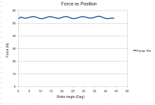
I do have some graphs to post though. Read, tweaked, read some more, tweaked some more – applied the same scripts to both the 9C 2806 RF and the 16p18t AF (with obvious customizations) and… it just begs for more questions. There’s even a Halbach version of the 16p18t… Biggest change was that I included the Force and the Torque for a full 2-pole cycle. The Force is calculated using the mo_blockintegral(18) method.

I found that Lorentz force blockintegral(11) which you initally suggested, provided more expected results for force. I'll have a look at your scripts and post some more feedback.

Kingfish said:
:idea: I do want to review the maximum Tesla that can be crammed through a thin back iron; that is key to factoring out design and manufacturing. I wonder what the permeability of CRS is.

Twiddlin’ KF

What is CRS? Permiabilty and saturation are similar but not related. Pure iron saturates at around 2.2T Laminated Iron at around 2T, Laminated Cobalt at around 2.3T. For high permiability you want Nickle. For Nickle see Mu Metal for an extreme example http://en.wikipedia.org/wiki/Mu-metal, or Carpenter "49" for something you can get in laminations, but you will notice that Carpenter 49, saturates at around 1T

http://cartech.ides.com/ImageDisplay.aspx?E=207&IMGURL=%2fCarpenterImages%2fC-MagneticControlled%2f01-EA01-CarpenterHighPermiability49Alloy%2f05_EA01_RotorGrade.gif&IMGTITLE=Rotor+Grade+-+Results+at+0.014%22+%280.36%22+mm+thick%29

from the rotor spec link here: http://cartech.ides.com/datasheet.aspx?i=103&e=207&c=TechArt

Carpenter Hyperco50 (cobalt alloy) is high saturation 2.4T , http://www.cartech.com/ssalloysprod.aspx?id=2360

From the simulations, I don't think the high flux dencity of the back iron is going to cause a significant problem for this motor like I initally thought. I haven't studied the simulations extremely closely, so I could still fall on either side of the fence for this decision.

-ryan
 
I confirmed that mo_blockintegral(18) doesnt' work for your application. mo_blockintegral (11) provides nice results (see attached image)

The Force at 10A RMS per phase is 54.4N with a ripple of about +-0.9N, so that is pretty smooth. Using the 76mm radius, that puts the torque at 4.1Nm.

At 1000 RPM, that translates to about 430W of power (1000 * pi / 30 * 4.1)

And that agrees with my previous statement of DC Kv of 46 RPM / Volt, which translates to 14.7V RMS per phase at 1000 RPM. 14.7 V * 10 A * 3 phases = 440W.

So both Electrial power, and mechanical power match up pretty close, which suggests that the simulation and analysis is accurate.

Have you figured out what the resistance of each phase it yet? how much power is going to be produced in the coils (I^2 * R) by the 10A RMS per phase?

-ryan
 

Attachments

  • Force Vs Position.png
    Force Vs Position.png
    4.5 KB · Views: 9,286
I forgot to mention, in the script, if you want to simulate more than 1/2 of an AC cycle, you can just change the phases_to_simulate variable from 0.5 to 1 or 2 or whatever rather than multiplying steps in the for loop. Also if you want to have smaller displacement between steps, increase the steps variable (right now in your simulation you have it set to 15, I put it at 15 because your first models took so long to solve, but now they are good and fast so you can do many more steps in the same amount of time). For analyzing the flux linkage and turning that into a BEMF I usually put it at something between 40 and 50 steps and 1/2 cycle. When computing cogging torque, I do 90 steps in 1/8 of a cycle.

-ryan
 
Hi Ryan

I'm on travel and can't get to my files for a few days. However I did want to ask kindly why you thought Lorentz (11) was better than Force (18). Just curious :)

CRS = Cold Rolled Steel. It is very common and sturdy. Requires painting or plating to prevent corrosion. The only Nickel alloy I considered was Stainless Steel (SST) 340 which is magnetic, strong enough, and modestly resistant to corrosion.

Stator: The inside of the coils could be aluminum 6061 or 70XX series, and have a thin carbon-fiber or fiberglass sheeting epoxied to each face, pressed and heat-cured. The ribbing would have to be integrated to the central hub interface, possibly water-jet cut from one plate.

I hope to get back to my studies this weekend :wink:

Cheers from abroad, KF
 
what, alu inside the coils? :shock:

Also, what lateral forces is it that was mentioned on the stator?
 
phyllis said:
what, alu inside the coils? :shock:

Also, what lateral forces is it that was mentioned on the stator?

I think he means that the hub, supporting the coils , not actually inside the coils is to be made of aluminum. Obviouly any (non-laminated) aluminum that is in the magnetic field of the rotor would cause significant eddy current loss.

Kingfish said:
Hi Ryan

I'm on travel and can't get to my files for a few days. However I did want to ask kindly why you thought Lorentz (11) was better than Force (18). Just curious :)

I'm not exactly sure, I havent' give it much though, because Lorentz just seemed to work. I think it has more to do with the loose meshing than anythign else, but the force while moving that you were finding seemed to have very large errors.
 
Plan-E eMoto AF DD Hub

It’s been a while since I posted on this thread and much has changed. Namely I completed a significant personal goal of riding my present eBike (P1 as 2WD) to California and back. This experience taught me a lot about how I want to use my next EV experiment, and I think I can quantifiably say without hesitation that next year I want to travel in the lane with all the rights and responsibility of a motorcycle. For the amount of time and energy I am spending to potentially create an AF motor, I just think it makes economic sense to go for it and produce an eMoto (I like that phrase) AF DD hub instead of an eBike version.

For one, I can discard the 200mm diameter limitation of trying to match a 9C-like physicality and attempting to mount it as a front hub on a DH 20mm-axle fork: All of that business of trying to stuff 10 lbs. into a 5-lbs sock is gone. We can start from a clean slate, and build with what we already learned. :wink:

Challenges:
This is actually a bigger leap than crafting a new bicycle; it will cost a lot more to acquire, manufacture, and assemble parts to complete a simplistic hub for testing.
  • Define the parameters of operation
  • Design a basic motor (Alpha)
  • Build a dyno (thread already started)
  • Acquire the appropriate equipment for repetitive measurement
  • Evaluate a base to test against (9C cos I have several)
  • Test and Perfect methods of assembly before committing to the 2nd-phase (Beta)
  • Then build a motorbike framework to support the final application.
I am going to start with the Plan-D model and change it accordingly to match the new specifications. The final bike will still utilize 2WD; I am totally happy with the utility for a number of reasons:
  • Redundancy (insurance)
  • Traction (safety)
  • Acceleration (thrill!)
  • Scalability (power)
Targets are:
  • Match the output of a 250cc motorcycle; about 24-28 hp, or 9-11 kW per wheel
  • Hold 75 mph at STP on level ground continuously for hours
  • Run efficiently; don’t be a power-hog
  • Run cool; presume there is some sort of active cooling both for the hub and the controller
  • Ease of Assembly
I will post the specs and math in a bit; I’m still putting together initial estimate and calculations, but it won’t be long.

Cheers, KF
PS - It is with hope that MRVass will run the MySQL scripts I provided so the corrupted characters will be fixed – making this entire thread much easier to read. :)
 
Initial changes between Plan-D and Plan-E:

  • Wheel is motorcycle, 110/70-17 (Front) & 130/70-17 (Rear). Doing the Math, it turns out they are about 24.1 inches in diameter when taking into account the tyre dimensions. This is nearly identical to Plan-D. However we are no longer constrained by factors of bicycles and can use most of the spoke length to our tremendous advantage.
    • Was: r = 90mm, or 0.090m
      Is now: r = 152.4mm, or 0.1524m
  • Horsepower has dramatically increased from 2, now up to 14.
  • Target Velocity has increased from 30 mph to 75 mph / 121 kmh.
  • Magnets are off-the-shelf at 0.75x1.5x.025 inches (19.05x38.1x6.35 mm) and available in a robust temperature range.
  • Poles and Teeth are the same: 32P (16:1), 30T (10T/phase)
  • Force and Torque have naturally changed; let’s Do the Math! :)

Calculate Rotation
  • Given Wheel Diameter (d) = 24.1 inches/ 0.61214m
    Circumference (C) = πd = 75.712 inches/ 1.9231m
    fps = (mph * 5280)/(60min * 60s) => (75 * 5280)/3600 = 110 fps or 33.528m/s
    rps = (110 fps * 12 ipf)/(75.712 inches) = 17.434 rps
    rpm = 17.434 rps * 60 seconds = 1046 rpm
Calculate Torque (τ)
  • Given: Power (P) (kW) = (τ (Nm) * 2π * rpm)/60000,
    τ = (P * 60000) / (2π * rpm)
    τ = (11 kW * 60000)/(2π * 1046) = 100.4 Nm
Calculate Angular Velocity (ω)
  • ω = 2π * rps
    ω = 2π * 17.434 = 109.5 rads/s
Check our work
  • P = τ * ω
    P = 100.4 * 109.5 = 10993.8 watts; an error of 0.06%... good enough :wink:

Calculate Motor Constant (K)
  • K = τ/ω
    K = 100.4 / 109.5 = 0.91668
    Kt = K/3 (3-Phase) = 0.30556
Calculate the Ideal Steady State
  • P = Current (I) * Voltage (V); solve for V
    We already know that V == τ, therefore
    V = 100.4 Volts, and I = 109.5 Amps
Solve for the Length of Conductor
  • Given: F = IL x B, where Force (F) = I * Length (L) x Magnetic Field (B)
    L = F/(IxB); Presume B = 0.5 Tesla, also written as L = τ/2rBI
    L = 100.4/(2 * (0.61214/2) * 0.5 * 109.5) = 2.995 m

Note: I need to switch to Nm/metric to complete the rest of the calcs. With exception to references wheel diameter and velocity, everything else with be in SI-units.

More in a bit, KF
 
More calcs...

Evaluate Conductor Length over a range of voltages
For this next series, presume that I am going to reuse my mini-mountain of lil’ LiPos, each brick being the 5S1P 5Ah 15/2C Zippy FlightMax. The calculation for I = P / requested V.
  • Vbatt = 63; 15S; I = 11000 / 63 = 174.6 Amps (A). Using L = τ/2rBI, L = 1.1789 m
  • Vbatt = 84; 20S; I = 130.9, L = 2.096 m
  • Vbatt = 105; 25S; I = 104.8, L = 3.275 m
  • Vbatt = 126; 30S; I = 87.3, L = 4.715 m
The relationship between current and voltage is interesting, though not precisely linear as we can see from the graph below.

GraphPlan-E.VoltagevsCurrent.png


Corrections
At this point we must reduce the value of r because it will never be equal to the radius of the tyre. The rim diameter is 17 inches; therefore I propose that we create an average magnetic diameter of 12 inches:

  • New r = (12 inches * 0.0254)/2 = 0.1524 m
In addition, the strength of the Magnetic field (B) will be more than 0.5 T; from my experience with FEMM we can presume this value will be > 0.65 T, so let’s pick that – being the optimistic designers of motors et al. :)

  • B = 0.65 unless otherwise noted.
Calculate Force
  • Force (F) is calculated as F = τ/2r
    F = 100.4 / (2 * (0.61214/2)) = 329.45 N
Note that the Force required in Plan-D was 377N; now we can appreciate the longer radius! :wink:

Recalculate the new Conductor length using 63 Vbatt
  • Given: L = τ/2rBI
    L = 100.4/(2 * 0.1524 * 0.65 * 174.6) = 9.5238 m
Calculate Frequency
  • Frequency (f) = rps * Number of Pole-Pairs (pp)
    32 poles = 16 pp
    f = 17.434 * 16 = 278.95 Hz

Calculate the Number of Turns per Tooth
We now have all the pieces of the puzzle to characterize the conductor and determine the number of turns per tooth for this motor. This is a 3-Phase motor, therefore…

  • Iphase = I/√3 => 174.6/√3 = 100.81 A
This motor has 30 teeth, 10/Phase, therefore…

  • Itooth = 100.81 / 10 = 10.081 A
Length of Conductor per tooth becomes...

  • Ltooth = Total L / #pp / # phases => 9.5238 / 16 / 3 = 0.3175 m
Magnet Length = 1.5 inches / 38.1 mm (a figure previously given)

Number of Turns can now be evaluated as...
  • #Turns = Ltooth / (2 * Magnet Length)
    #Turns = 0.3175 m / (2 * 0.0381 m) = 4.2

More... KF
 
Stator Redesign

I spent a good deal of time investigating Magnetic Wire and Litz Wire, and this and that… When yer On the Road for tens of miles it gives a person plenty of time to think about these things, and I have come to the realization that whatever I create – I must adhere to the principle of K.I.S.S.

How do we solve to make the stator dead-simple and solid-state? I take no credit; it belongs to Goethe who proposed early on Page 3 of this thread to use a PCB. The value of this suggestion weighed heavy and the more I pedaled, the more sense it made for a number of reasons:

  • Fabrication is automated; remit the design to the manufacturer and in return is a finished product with greatly reduced labor costs.
  • Waterproof
  • Temperature-tolerant & stable
  • Multilayer construction, rigid, stiff
  • Thick copper plating can be used to draw heat away if designed appropriately

a2.jpg

An example of a PCB-Stator.

Moving right along…

Calculate Trace Width
I used a website provided in another thread called appropriately enough: PCB Trace Width Calculator. The following values were used:

  • Trace Current = 10.08 A
  • Copper Plate Thickness = 3 oz./ft^2
  • Temperature Rise = 10°C
  • Trace Length = 0.318 m
Results:
  • Internal Trace Width = 6.31 mm (1/4 inch), and external exposed to air = 2.42 mm.
  • Power loss = 0.862 w for internal and 2.24 w for external.
From this calculation the trace is hugely phat. We can skinny-up this guy by increasing the copper plating, allowing a temperature rise up to 30°C, accessing the multilayer features by creating parallel traces, and by reducing the current if we elect a higher voltage. So far we’ve been looking at a single stator; we could easily add another stator-rotor pair and split the load. All can be done and are possible.

At this point though we have enough information where modeling in FEMM can begin. 8)

Enjoy, KF
 
Kingfish,

I've been trying to email you through Hordoffun, and PM through the forum, with the digital demons fighting me.

Would you please contact me directly at:

matt.cheresh@lightweightmagnetics.com?

Thank you in advance.

Matt Cheresh
 
Greetings ye kindred ES folks

My wheels of progress have not been idle. I have a correction, a typo on the reporting; apologies to anyone trying to replicate the math.

On Sun Oct 02, 2011 5:03 pm, I posted the following formula:
Calculate Force
  • Force (F) is calculated as F = τ/2r
    F = 100.4 / (2 * (0.61214/2)) = 329.45 N
This is incorrect; it should be
  • F = 100.4 / (2 * (0.1524)) = 329.45 N
The error was caught when I reviewed the maths for another project.

Electric Steel
I am presently struggling with an appropriate back-iron material, and let me state clearly what I mean cos I could have the interpretation incorrectly applied: I am modeling an ironless core/stator. The back-iron is for the backside of the magnets. For example: The 9C hub has back-iron along the perimeter of the magnet ring to close the flux.

A couple of bright sparks out there have told me to keep the magnetic flux density (B) below 2T. It could be that I am modeling incorrectly, though it seems that FEMM does not discriminate well between using Iron or M-19; no significant effect upon B. The real question though is whether to evaluate B when the system is at 0hz or when it is at 100%-rated frequency because that does make a big difference in the amount of material thickness.

In addition, should I consider the frequency of the PWM as a factor when selecting the proper material? The motor frequency (f) I have calculated as rps * pole-pairs; this value is < 300 Hz for 75 mph.

That’s all I have for the moment. I’m just working away in my hidden urban bat cave, buffing and polishing the model, trying this and that.

Now if I can just get Alfred to make a proper batch of beer… 8)
Magnetized, KF
 
Keep in mind, fiberglass is a good insulator, and the continuous torque a motor can make always comes back to the amount of heat you can shed.

There are a TON of various PCB axial flux motors out there, and kits you can buy off the shelf with PCB stators for axial flux motors. You may want to compare there results with power and torque density vs non-pcb motors to make sure you're getting into something that makes sense.
 
About heat: Yes, I agree – that is a very salient point and one I wanted to address immediately after the electric steel question. I discovered from one fabricator that they rate their FR-4 boards only up to 120°C; good to know for spec’ing magnets. The downside is that’s quite a bit less than what iron-core stators can accept. Regardless, you’ve raised a very good point indeed.

For lab study FR-4 would probably work fine on the proof-of-concept model where the heat can be managed. Whatever is chosen for the final product, it has to be mechanically-strong under shear with very low deflection, forgiving/not brittle, and electrically isolated -natch.

~KF
 
liveforphysics said:
Keep in mind, fiberglass is a good insulator, and the continuous torque a motor can make always comes back to the amount of heat you can shed.

About shedding heat from an axial flux motor... I've always wondered about this.

DSC00299.JPG

This is my home-made motor. The heat is generated by the current flowing through the resistive coils in the (here acryllic glass) stator.
Left en right of the stator is a plate with magnets. I've always wondered about the airflow generated by the fast moving rotor.
Looking at the picture, I think air will enter the rotor through the big hole where the axle is. This air will then be 'grabbed' by the
rotor and flung outwards through the small slot between the rotor and stator. This will create an airflow over the stator and in
this manner transport away the heat in the coils.
I can imagine at the moment this effect in my motor is negligible but that by adding a few scoops or vanes (Don't know what they're
call in english, the things you find on an old paddle steamer boat) it can be increased to generete a sufficiently large airflow.
 
I love all your awesome work on motors and controllers Lebowski. Very very cool stuff.

I agree with your airpath thoughts, and it wouldn't take much for vanes to make it move some air if you spin it fast enough. Air moves at the square of RPM in those types of pumps, so you get roughly nothing at low speeds, and then at high speeds it comes on strong.
 
I've thought about PCB-stator axial-flux motors before. It's an attractive idea from the ease-of-manufacture standpoint. Luke is right that heat will always be an issue, also you'll likely never achieve the same kind of power density as a conventional stator design because the copper fill is fairly low (lots of fiberglass volume compared to copper). However, I don't think these are necessarily fatal flaws.

One way to improve the copper fill would be to go to a multi-layer board design. 4, 6, even more layers, possibly with the same coil pattern on each wired in parallel. The big disadvantage here is heat in the inner layers, as they will be fairly well insulated by the fiberglass. A possible solution might be to go with quite heavy copper on the outer layers and the standard 1/2-oz in the inner. The relative resistances will ensure that most of the current flows on the outer layers, to keep heat under control in the inner layers. A generous amount of vias would also help conduct heat to the outer layers where it has a chance to be removed by airflow. Multi-layer boards are more expensive, though, so it might be more economical to just use a 2-layer board with super-heavy copper. You might be able to use a thinner board than the standard 0.062", although there would be a tradeoff in structural rigidity.

I think the big thing to extract both reasonable power and reasonable power density would be to a) make the air gap super-small and b) use a multi-stator design. Since the PCB is thin and has good manufacturing tolerances, you could make the air gap very narrow, less than 0.1". That would give you very good flux density in the gap and thus a better Kt value, which would take the sting away from the lower current density. Now stack 3, 4, 5 of those stators together with n+1 magnet rotors, and you could probably get to some useful values of torque and power.

I don't think this would ever be a super-high performance design along the lines of what Luke likes. :) But, it might be something relatively simple to build, and perhaps an interesting engineering challenge to see what can be extracted.
 
Eric, that is precisely the route I am studying: Multilayer board with heavy copper clad, fat as I can fit traces. I use the PCB Trace Width Calculator to characterize options and note the heat rise. Don’t want a lot of heat; bad for business.

The problem with parallel traces though is that the current will never balance, so instead I thought of running the turns in series through the layers for a higher count, and then each stator is in parallel as you suggested with at least 2 stators and 3 rotors – as a starting point. Adding one more stator-rotor pair increases the output (F) by roughly √2; not quite 50% - but hey we’re already here so let’s throw another log on the fire.

The part where I took a tangent this last week is exploring how more turns reduce the current, but then we’re going to get more resistance (heat) and require more voltage. I’ve crafted a pretty happy model, though I don’t yet know how to get it to report the voltage back out; losses – yes, wattage – yes, system voltage - no. Running the Lua scripts is incouraging though. If the magnets didn't cost a kidney I would order up 256 pieces right now :lol:

For the pcb, I am thinking 3.175mm (1/8th inch) thick FR-4 to initialize the proof-of-concept stator, although I am searching for a tougher laminated substrate. Toying with a heat sink idea: Wouldn’t a couple of layers of solid copper work to pull heat from the board so long as I didn’t fill the center of the windings?

Electric Steel
Been doing my reading and modeling on M-19, M-4, plain iron from McMaster-Carr (not the ductile stuff) 1018 and 1006 Steel. The “Iron” material in FEMM performs the best, and all other materials appear to reduce the flux density (B) – and it has to be at least ¼ inch thick to drop B below 2T at 100% frequency; at 0Hz the flux ring is supersaturated above 5T.

The devil’s in the details: Hate to sell my real soul, though I might sell’m my leather sole… he can have both of them. :twisted:

~KF
 
Kingfish said:
The problem with parallel traces though is that the current will never balance, so instead I thought of running the turns in series through the layers for a higher count, and then each stator is in parallel

Does it matter if the current balance is perfect? If the copper on each layer is identical and they're connected in parallel, it's something akin to stranded wire. If more current flows through the (thicker) outer layers, then less heat will be generated in the inner layers where it's hard to get rid of.

Kingfish said:
Adding one more stator-rotor pair increases the output (F) by roughly √2; not quite 50%

I don't think I understand why it wouldn't be a 2x increase in torque. Is there some other factor you're including that partially cancels that out?

Kingfish said:
Toying with a heat sink idea: Wouldn’t a couple of layers of solid copper work to pull heat from the board so long as I didn’t fill the center of the windings?

That would help with the heat, but eddy currents would bite you instead.
 
You need to make use of every bit of copper available. If it's a 6 layer board or something, each layer needs to be as thick of copper as they make, then you need to figure out how many turns you're going to need (which is going to be a lot with no core if you want to have reasonable inductance), and then you need to make every layer as thick as physically possible to get the number of turns in you need. Anywhere you made it less thick would just be additional resistive loss and heating in an area that is all ready going to be nearly impossible to cool. The concept of balancing thickness between inside and outside layers is fundamentally flawed, you need to just do anything possible to reduce copper losses, and the layers should all be parallel. The ones that heat up faster will increase in resistance and get less of the current load naturally.

You're going to be in a situation where it may be impossible to even get 10% copper fill factor (haven't worked the math though, maybe you can find some super thick trace PCBs?" You are going to have extremely low continuous power, lots of motor heating problems, and lower than typical safe motor coil temperatures as well.

Keep in mind, even the 98% efficient CISRO motor would burn up at just 1.8kw, and it had WAY better copper fill and WAY higher efficiency than is even theoretically possible with your design.
 
A couple of loose thoughts:

1) Multilayer may get you a board so heavy that you'll drill holes to reduce weight - drill plated holes near the tracks to increase heat dissipation

2) Increase motor diameter - more torque. I've played a few time with this idea of having a motor almost as large as a wheel. It would have coils (maybe magnets; never really decided on that) and a comutator with brushes at the highest point, fixed to the bike's frame, with some magnets. The increased diameter would compensate for the "single pole".
 
liveforphysics said:
You need to make use of every bit of copper available. If it's a 6 layer board or something, each layer needs to be as thick of copper as they make, then you need to figure out how many turns you're going to need (which is going to be a lot with no core if you want to have reasonable inductance), and then you need to make every layer as thick as physically possible to get the number of turns in you need. Anywhere you made it less thick would just be additional resistive loss and heating in an area that is all ready going to be nearly impossible to cool. The concept of balancing thickness between inside and outside layers is fundamentally flawed, you need to just do anything possible to reduce copper losses, and the layers should all be parallel. The ones that heat up faster will increase in resistance and get less of the current load naturally.

Totally agree with you that having as much copper as possible is desirable. I don't think you can rely on the thermal coefficient of resistance to handle the balancing, however. If you assume that 120 C is the maximum allowed temp, copper only has 39% more resistance at 120 C than at 20 C. That's not going to be enough to do much balancing if the inner layers don't have a path to dissipate heat. They'll just get too hot and de-laminate the board.

With a multi-layer board, I don't think there's any way around it except that you'd have to use a huge number of vias to conduct heat outward. If you did that, then the heat transfer might be good enough that you could use thick copper on all layers and rely on the thermal coefficient to regulate things.

Copper fill is definitely going to be low. Just tossing out some numbers, 6-oz copper would be 8.4 mils thick. If you put that on a regular 2-layer board with 60-mil FR4, it's about 28% copper by volume. Once you start actually cutting the traces that'll drop, so maybe 15-20% at best. You might be able to hit 50% if you do a really custom board with 6,8 layers of heavy copper and thin FR4 between.

You'd definitely want to make it as big (radius) as feasible. The issue there is that it's going to be hella expensive to make big, custom PCBs that you're only using the outer 2-3" of. I had an idea that you could maybe design it in partial arcs so that one PCB would be an arc-shaped piece, maybe containing a unit of 3 coils. It would be much more space-efficient to tile a bunch of those onto a sheet of material. Then you'd assemble the stator by stacking them together in an over-lapping fashion (there would be some important details in exactly how this was done, and you might end up needing some extra structure to stiffen the assembly).
 
I would take some 2 x 4 mm copper bar, isolate it by sheeting it with heatshrink tubing. Wind the bar
in a flat coil, solder one opposite it so you got a 4 mm thick structure with the connections on the outside
of the flat circular coils. Make a mould, put in all your coils, add epoxy et viola, there you have your coil plate.
 
Lots of good comments! Thanks Gents 8)

For the record, I am working on the assumption that the operation limit is set to 120°C which keeps us in the game for good strong commercial magnets.

The way I went about calculating the stator was to approach the problem with the following in mind:

  • Maximize the average radius to reduce the required Force (F) which in turn reduces the required current (A).
  • Calculate the Length of conductor for a single stator.
  • Maximize the length of the magnet.
  • Calculate the number of Turns per Tooth.
  • Using the Inner-Trace limitations and clamping the rise to 15°C, figure the thickest & width of the trace for the current with the acceptable maximum temperature rise.
    • Conclusion: The trace will never fit.
  • Add a matching layer and recalculate with layers in parallel. This eventually winds up being a very fat pcb. Using FEMM, the thickness proved counterproductive by reducing the flux density between the rotors.
    • Solution: Add another stator/rotor of the same parameters and twiddle. The overall current drops per stator and the traces can be reduced further. I followed this development path all the way to 5 stators. (Shall we say ‘Money no object’?)

That’s where I was at about a month ago. I had a long commute into Seattle and there was time to kanoodle with different ideas… that’s when I thought about breaking form and going with more turns in series rather than parallel turns. Using that methodology I was able to save a layer for each stator, reduce the number of stators, and drop the current substantially with FEMM affirming the results both modeled statically and with the LUA scripts provided by Biff.

However – I don’t think these stators can be built. It would require vias between layers and how do you plate that? I’m a pretty clever guy; perhaps once I get into doing the design layout it might become self-evident, though it would be a challenge. To be certain I really need to speak to some quality pcb manufacturers to determine the limitations of manufacturing. The problem is that I am not convinced that FR4 will be the final production material.

  • Specifically, what is the thickest copper cladding possible for inner layers, and at what cost?
  • Dimensionally, most pcb houses can craft a board the size I need; that’s not a problem.
  • What is the thinnest possible lamination? We’re talking voltages less than 200, so I know the dielectric can withstand whatever we throw at it.
  • What other types of laminate can be used?

I’m open to other ways of constructing a stator – it’s just that the pcb or laminated-process has a great appeal in terms of unitizing manufacturing: Tooling-wise I think it would be less expensive and laborious.

Would someone care to take a stab at my original question about electric steel material candidates? :twisted:

Most appreciative, KF
 
Back
Top