Science, Physics, Math, & Myth

Punx, is there a certain ratio of stator diameter to overall wheel diameter that is ideal? A Sweet spot. Miles looked at weight vs torque- efficiency on the ultimate hub thread. Stator width to diameter ratio that is ideal? My guess when looking at making a motor able to stall more often / longer without burning up, the larger the diameter ratio (motor stator to wheel diameter) the better, more than anything you can do in the control or winding options. There are tons of other things that can be tweaked.

To make revolutionary levels of improvement, many times it takes dozens of tiny ones added together.
 
Probably, but I'm not smart enough to know what it is ;) Ideally the motor radius would be the same as the wheel rim, but that means more (and stiffer) supporting structure for the stator, which carries a weigh penalty. So I guess the "sweet spot" is an acceptable compromise between torque and weight.
 
Punx0r said:
Probably, but I'm not smart enough to know what it is ;) Ideally the motor radius would be the same as the wheel rim, but that means more (and stiffer) supporting structure for the stator, which carries a weigh penalty.

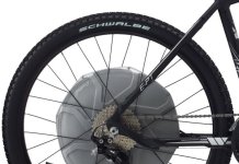
You can look at the BionX "D" series hub motor for some inspiration on that front. They eliminated the structural load on the hub motor shell by having a separate very conventional metal spoke flange for lacing the rim into, allowing them to use a lightweight composite support structure to hold large diameter magnet ring since it was then no longer load bearing. The end result is a hub motor with definitely better torque/weight ratio of anything else in that power class. And the resulting magnet to tire diameter ratio in a 26" wheel is > 0.5, better than the 0.4 ratio you get with most of the generic (mxus, 9C, crystalyte 'H' etc.) hub motors in a 20" wheel.
D Series.jpg

So I guess the "sweet spot" is an acceptable compromise between torque and weight.

There's also the question of aesthetics of course. Personally I'd take a slightly heavier motor that looks smaller than a giant disk wheel. Unless they made it hollow in the middle, then it might b become cool again.
 
Punx0r said:
Larger diameter = winning.

No, highest efficiency for the power you require is winning, and the motors I use win that by a long shot, and they have a stator diameter of only 189mm and 60mm stack of lams. The problem with increasing diameter is that it requires a lot more stator steel and copper to avoid going to high slot and pole counts, which is the cheap way to make hubbies that results in lower efficiency.

My favorite hubbies have the dimensions above, but I also have one with a 270mm diameter 50mm wide stator. That have almost identical Kv's, so there torque per amp is almost identical. The bigger one is also much heavier, but a bit lower resistance, so it has better current handling. It's real limitation is the high core losses resulting from the high pole count, so it's quite speed limited by comparison.

The only advantages I see to larger diameter motors are:
They're easier to keep narrow and still produce high power.
The larger diameter give them more surface area for better heat dissipation, which is good since their lower efficiency demands it. 8)
 
Great point, Justin, I'd forgotten about the novel Bionix design.

John, what's wrong with a high slot/pole count? Sure, core losses become excessive at some point and you need a controller with a high eRPM, but for a large diameter/low speed application like a bicycle I see good things for a large diameter motor with lots of little teeth. Imagine having 26" or 29" wheels and still be able to climb steep offroad slopes. It's just mechanical advantage for the motor, much like going to a smaller wheel :)
 
Justin brings in a great point on hollowing out the center of the hub design. Some simple rethinks of existing design constraints can eliminate most of the center mass issues as miles did in some of the ultimate hub concept drawings. Steel can be greatly reduced as he did also.

Is there a ideal magnet / pole width? Does a larger diameter allow wider (same degrees or arc) magnets / poles as its smaller counterpart. Are we able to run multiple smaller teeth/poles in parallel? How much loss is there from running less steel at higher saturation levels? I would think at bicycle power levels, less steel at low lower current levels may not be a huge penalty. Am I way off on this? Questions are meant to be rhetorical and only to help find a direction where improvement pay dirt can be easily explored/ reached /evaluated.
 
Punx0r said:
Great point, Justin, I'd forgotten about the novel Bionix design.

John, what's wrong with a high slot/pole count? Sure, core losses become excessive at some point and you need a controller with a high eRPM, but for a large diameter/low speed application like a bicycle I see good things for a large diameter motor with lots of little teeth. Imagine having 26" or 29" wheels and still be able to climb steep offroad slopes. It's just mechanical advantage for the motor, much like going to a smaller wheel :)

There's nothing "wrong" with it, but looking at it from only the standpoint of having a longer lever doesn't consider that the lever is skinnier. ie The small teeth have a lower saturation point, so the mechanical advantage is offset a lower torque limitation, otherwise the Magic Pie large diameter motors would be the hit of the forum. At pedal bike speeds anything works. I demand the power to match car speeds, and living in a mountainous area where flat is rare things become more challenging, and efficiency and heat dissipation are what matter. To me efficiency is king, since that also makes best use of the most expensive part of our systems, the battery, and it minimized the heat to be dissipated. I'm not talking about just peak efficiency of the motor, but also having enough motor that it runs at low stress for greater overall efficiency.


John
 
speedmd said:
Is the magic pie available without a tiny dedicated controller and in higher KV form? Would be interesting to see what some ES hot rods could do with it if it was more open source on the control side.

the problem with the magic pie is the stator laminations have 0,5mm. If it would have 0,33 or even 0,2 made of good steel, im sure it would be more widely used.
I have seen RC model plane builders (for speed records and racing) who spin theire motors up to 200kermp, yes 200000 ermp! they use motors with 0,2mm lams and i even have seen one with 0,1mm.
 
markz said:
I thought thicker/bigger is better for lam's
It that was the case then why use lams at all?
 
Arlo1 said:
markz said:
I thought thicker/bigger is better for lam's
It that was the case then why use lams at all?
What Arlo is saying is that thinner is better. There are less Eddy Current losses as the lams get thinner. Also less "cogging resistance" with a thinner lamination.
 
....to keep this going, b/c it interests me..........

The Laminations themselves you want as thinner, what about the overall thickness of the total # of lams?
 
You want thin laminations to improve overall efficiency and minimize eddy current losses. Wider overall stators (stack of laminated steel sheets) lower the Kv and increase the Kt of any given motor design, compared to the same motor design with a narrower stator. The change in Kv and Kt is linear, based on the overall stator width. If you double the stator width, the Kv is cut in 1/2 and the Kt is doubled.

For example, a MXUS "1000W" DD Hub motor with a 28mm stator, and a 10X6T winding has a Kv of about 9.5 RPM per volt, and a Kt of 0.74 Ft-Lbs of torque per amp. The same motor design with a 45mm stator (MXUS 3000W) with the exact same winding pattern would have a Kv of 5.9 RPM per volt and a Kt of 1.19 Ft-lbs of torque per amp. If you compare the Stator widths, the 45mm is 1.61 X wider than the 28mm motor, so the Kv is 1.61 X slower, and the Kt is 1.61 X higher.

I think we already understand well that changing the winding to a lower turn-count increases the Kv of a motor. - In the case of the comparison of the 28mm and 45mm motors, to keep the Kv and Kt roughly the same, the wider stator would need to have fewer turns of the winding. As an example, the 10X6T winding of the 28mm motor has roughly the same Kv as the 16X4T winding of the 45mm stator. This is where the power increase happens. Since the 16X4T winding has 60% more strands in parallel, the wider stator motor can handle 60% more total current, than the narrow stator motor. This change in winding cross section, while keeping Kv roughly the same, is ultimately how a wider stator motor is more powerful than it's narrow stator cousin.
 
Speaking of laminations I'm getting skateboard hub motors made in China and am wondering how good the stator will be. It's .2mm laminations which sounds great but how about the "induction" and "core losses"? I don't have any referenceimage.jpg


The motors are intended for voltage between 22 and 40 volts, which is a big spread, and can't decide on what kv to get them wound to. As it is now they are going to do them to 100kv and the wattage of each motor will drop to 1500watts and they are recommending a higher kv. The motors are 47mm diameter stator,25mm long, with (14) n45h magnets rolling a 80mm wheel. 25mph max sounds good

They might be able to squeeze in hall sensors, will they make things quieter? It seems every hobby esc screeches awfully when braking. How do the commercial boards keep quiet?
 
That is decent material and 0.2mm is adequately thin unless you're going for extreme RPM.
 
At first I thought 100Kv was huge, until I read this

http://www.recumbents.com/wisil/e-bent/rc_drive/tutorial.htm
Typical E-bike RC motors run at 8,000 to 12,000 RPM with no load. In general this means with a 50V battery pack you will want a KV of 225 or lower.

Hummina Shadeeba are you buying skateboard RC motors?
 
image.jpggetting them made. u cant buy hubmotors except for some adapted hobbyking outrunners which dont really have the motor recessed all the way, and dont have the best rubber

i cant upload a pic of the design on this ancient ipad but the manufacturer moved the stator and im wondering if it was to reduce eddy currents. are eddy currents produced by the stators changing polarilty or is more so due to the moving magnets? i imagine both. i have a non-moving aluminum wall right beside the stator and not far from the spinning mags of the rotor, or the stator can be pushed to a steel wall that revolves the mags and thats what they did

at what point do eddy currents become an eddy current brake or it a matter of degrees?

ill post a design pic when i get on a recent machine


i remember my other question. when a stator is "saturated" it is really just the end of the tooth that is saturated right? so if i put magnets down the rotor wall maybe i could utilize more of the stator? so instead of an i terface that was purely cylinderical i would use the flat wall on one side of the stator and these magnets would spin with the rotor. or maybe add them to the aluminum wall and it would reflect the flux and produce no eddy currents there. or. bismuth or mumetal maybe on the aluminum wall. ill put up a pic in an hour and thatll make it easier to visualize.
 
in a scenario in which a high kv motor is run without the optimum volt to amp ratio..so too many volts, what happens to all the volts when the motor is run?
the high kv says it will suck a lot of amps to make up for the lack of inductance the motor will produce due to thick and few windings but what about the voltage? in such a situation you'd want a battery with fewer volts and more amp hours...but if you didn't do that...are the volts just turned to waste heat? i didn't think volts produced heat.
 
Volts is your speed, higher voltage the higher your speed.
More amps more torque, but also just a little more speed.

V x A = Watts
V x Amp Hour = Watt Hours

So you can increase amps and decrease Volts and still have same watts.

Im sure others will "chime" in with other comments and suggestions and solutions and such.
 
Hummina Shadeeba said:
in a scenario in which a high kv motor is run without the optimum volt to amp ratio..so too many volts, what happens to all the volts when the motor is run?
the high kv says it will suck a lot of amps to make up for the lack of inductance the motor will produce due to thick and few windings but what about the voltage? in such a situation you'd want a battery with fewer volts and more amp hours...but if you didn't do that...are the volts just turned to waste heat? i didn't think volts produced heat.

The controller converts the pack voltage down to the voltage the motor needs for a given speed. The situation you speak of is where my bike is now using a 30s pack, though the entire system can handle the current levels for incredible acceleration and has no issues all the way to top speed. My typical riding is mostly below half speed, and except when I get on the highway I ride the same as I did when I ran a 20s pack. In daily lower speed use the system seems less efficient (consumption 5-10wh/mile higher), but the motor doesn't show more heat.

The controllers do run warmer than my others did, so I'm pretty sure that's where the extra losses are. I believe that is due to the greater step down in voltage to motor voltage being less efficient like is commonly true with voltage conversions...The bigger the voltage spread, the less efficient it is.

It could just be perception, and though I think I'm going the same or lower speed, I'm actually using some of the extra performance on tap. The warmer controllers tells me differently, though I guess these higher voltage controllers could simply be less efficient.

When you run higher than necessary voltage, you do want to be careful with phase current limits, because low partial throttle under higher loads like hills can result in greater phase current multiplication which can be dangerous for controllers. Otherwise there aren't ill effects, and the controller simply takes less battery current at the higher voltage and steps it down to lower voltage and higher current to the motor as needed, just like any time you aren't running at top speed for a given voltage.
 
Just to add info for comparison, At interbike i spoke with the engineer of BionX and they confirmed to me that the stator of their new larger diameter motor is 1cm width. And that most of the motor structure is made of special plastic.

Doc
 
Ugh. Where am I wrong here. A motor produces flux solely based on amps. Voltage will increase the amps going through but it's still just amps moving the motor. The voltage of those amps isn't important at the interface between wound too and magnet when it comes to making flux. Where did the volts go and what are they good for other than giving a higher potential top speed?

John this is/was my question but in your unrelated answer...you bring up a question. Are you saying running more voltsge than the esc can take is good with being easy on the amps? I imagine doing that would be with a specific esc or is it universal in what you're doing? Or maybe I'm wrong in what your saying. I thought there was no change in voltage from battery all the way to the motor regardless of speed it was running and it was just chopped on to off at different frequency.
 
Back
Top