Eastwood’s first battery build

you want nickel plated stuff when any moisture is present.

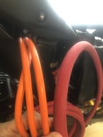
Yes I agree. I typically always use marine grade/tinned copper wires and lugs. Although this time my busbars are bare copper no nickel coating. Then also, the terminals on my 3Shul controller are non tinned Cooper. So I figured would just stick with bare copper wire, since nothing else has protection. Nothing will come in direct contact with Water.

Talking about wicking moisture after you crimp your 4/0 wire into a lug wouldn't you solder the copper wire ends at the end that points out the end of the lug so moisture doesn't weep in ?

Solder on the ends? These lugs only have one hole so once it’s crimped, it’s sealed with heat strink.
01C65C0B-B9ED-4378-AA5E-185350128ECF.jpeg
Plus how's that new spot welder of yours working. What do you find most useful the two pens the one handed handle or it looks like you put the machine on its end and plug in the lever activated spot welder attachment.
I was hoping just to get away with the handheld pens but I'm doing 120 cells so. ? Thanks

Haven’t tested the spot welder yet, will soon though!
Still have been ordering materials for this battery build but think of got everything on order now and the battery assembly will start soon. Ordered the BMS today, the 380a continuous 950peak version. Went with the 2.4” display.
 
Solid copper without tin - you will probably have surface corrosion, so for this apply Ox-GARD on the mating surface and coat the rest with a thin layer.

Lugs - Ancor and other brands have tin plated 4/0 lugs, copper/tin both cases, you want to protect the mating surfaces.

Stranded - No on soldering, it makes that lug brittle from what I have read, you want to saturate the strands with ox-gard and then crimp. and then apply ox-gard on the exposed ends.
 
So was just doing some test spot welds on some old recovered laptop cells. The spot welder seems to be strong. When I pull the nickel strip off the cells it rips and leaves the welded spot connected.

My question is how strong of a weld do I need? is there a standard protocol when test pulling on the welded nickel strips?

The welder adjustment goes from 1 to 99 and seems to get good welds at around 45-ish. When adjusted to around 30-ish the welds are decent, but you can pull the strips off with enough force without tearing the nickel strip. When set to 45 the welds stay connected, while the rest of the nickel strip tears away.

I’m using .15mm nickel strip as that’s the same that’s connected to my copper busbars. Thankfully, the seller sent me an extra copper busbar with the nickel strips so I can use that for my final testing, but I’m just using some standard nickel strip for this initial testing.2DDFC553-93E6-4936-9079-88615EDCF0CA.jpeg9D52079E-11AC-458E-9986-5F7D63B5302E.jpeg

Here’s a pic of the actual busbars I’ll be using

333258FA-C988-4A01-A82F-74E7777B1D24.jpeg
 
So was just doing some test spot welds on some old recovered laptop cells. The spot welder seems to be strong. When I pull the nickel strip off the cells it rips and leaves the welded spot connected.

My question is how strong of a weld do I need? is there a standard protocol when test pulling on the welded nickel strips?

The welder adjustment goes from 1 to 99 and seems to get good welds at around 45-ish. When adjusted to around 30-ish the welds are decent, but you can pull the strips off with enough force without tearing the nickel strip. When set to 45 the welds stay connected, while the rest of the nickel strip tears away.

I’m using .15mm nickel strip as that’s the same that’s connected to my copper busbars. Thankfully, the seller sent me an extra copper busbar with the nickel strips so I can use that for my final testing, but I’m just using some standard nickel strip for this initial testing.View attachment 337821View attachment 337822

Here’s a pic of the actual busbars I’ll be using

View attachment 337823
Here’s some more welds with the setting at 45. It seems to be bonding well to the batteries negative terminal but I’m so new to this.
Thoughts?
D0D8124D-50EB-483D-9D14-8852FBEAEA7D.jpeg8BC8251E-259D-45AE-A5A0-CA302EF0645F.jpeg8909AAC7-502E-4FF1-AA34-3067228B0BBB.jpeg
 
Here’s some more welds with the setting at 45. It seems to be bonding well to the batteries negative terminal but I’m so new to this.
Thoughts?
View attachment 337834View attachment 337836
You're good. You'll just want to pay close attention to the first round of welds on the actual busbars to make sure you're getting similar results. Their nickel will vary from what you're testing on now, therefore you may need a different power level.
 
Their nickel will vary from what you're testing on now, therefore you may need a different power level.
yep, I have one spare piece of that copper busbar with the nickel composite strips and I’ll do the final testing on that to get the right power level. I’ve noticed the nickel strip is copper on the bottom side so it’s some type of composite as the seller says.
 
My question is how strong of a weld do I need? is there a standard protocol when test pulling on the welded nickel strips?

Basic idea should be:

You want welds that like any other weld create a single piece of metal for the whole area of the weld, without burning thru the metal on either side.

You also don't want to penetrate into the cell itself, potentially damaging the "jellyroll" inside.

Keep in mind that all of the curent the cell produces in the system has to flow thru these welds, so you will have a lower resistance connection the more total welded surface area there is, so there will be less power wasted as heat inside the pack and more availble to your system. (you'll also have some higher resistance connection via any flat metal just touching the cell end surface, but it's not as good as the welded area)

The catch is that the more welds you do, the more chances to mess one up in a way that damages something, if you are using manually controlled probe force/etc, rather than something you can experiment with, find the right setting, and then have the computer replicate exactly on every weld.

I haven't actually built any welded packs, so I don't have the experience of what you would actually see...but the various spotwelder / tab / sandwich / etc threads do have some pics of bad vs good.
 
I saw that you have the lever, the handheld device do you also have the pens ? And which of the welding options did you use. As A.W. mentioned consistency. And I wanted to use just pens. Which seem might be the least consistent device ?
What is the thickness of the nickel or nickel composite in your copper bus bars and what is the thickness of your copper. Maybe you can measure it in gauge ?
 
I saw that you have the lever, the handheld device do you also have the pens ? And which of the welding options did you use. As A.W. mentioned consistency. And I wanted to use just pens. Which seem might be the least consistent device ?

I’ve been using the welding pen for the testing and plan to use that. The other welding device that attaches to the machine would not be long enough to weld some of the cells toward the middle of each section/level.

The welding pens seems to be consistent after about 30 practice welds, but will keep a close eye once I start doing hundreds of welds for consistency.
What is the thickness of the nickel or nickel composite in your copper bus bars and what is the thickness of your copper. Maybe you can measure it in gauge ?
The busbars are 1.0mm copper, the welding strip part is 0.15mm nickel copper composite.
Those buss bars are absolutely beautiful.
Have you shared this E.S. thread with Ken ?

Yeah, Wellgo does a great job at making these busbars.
No, I haven’t shared this thread with Ken.
 
Got some welds laid down, just the 1st ply as the battery is 4ply/levels. Posted pics on my build thread as well. The spot welder did great and stayed consistent. There wasn’t any heat buildup in the pen or the welding with 132 spot welds. Hoping this welder stays consistent throughout this build.

I have to say, it’s pretty satisfying spotwelding battery cells 😌


04DAF973-09D5-4041-91E1-6FAC93376CA2.jpeg
 
This 4/0 AWG is super thick! Never worked with wire this beefy before. The wire size is overkill, but it’s all in effort to get the least amount of resistance as possible. 10ft of this 4/0 AWG weighs 7 pounds. Should only need about half of the 10ft so maybe around 3ish pounds of discharge wires 😅
4CFA7FBE-135F-4550-807D-B9493AE5024F.jpegB1E74F9A-53BC-4D3A-A79F-F8306F6F7F92.jpeg

Much thicker than the stock phase wires 👇 from the qs138 v3. Plan to upgrade the phase wires.

3314BEAC-0F08-4DF6-A07F-08A643CDA446.jpeg
 

Attachments

  • 881506A3-88C1-4F5C-B8A1-681D80BB09D7.jpeg
    881506A3-88C1-4F5C-B8A1-681D80BB09D7.jpeg
    1.1 MB · Views: 5
Thinking about using this battery switch for my main contact and pre-charge, would be simpler to setup vs using the coil contactor through a switch. The coil contactor would need a step down to activate the coil 9-36v.
So was thinking it would be simpler to set up with using this battery switch..

1 - thoughts on this set up with using this BEP battery switch??

2 - Can someone please tell me what size resistor I need for the precharge?


BEP 771-S-EZ
400A Continuous / 600A 5 minutes Intermittent / 1500A 10 seconds

AD553475-FEAD-4DCF-9F9B-84319FCB8243.jpeg
 
Depends on how long you want to take for precharge, and the capacitance of your controller, and the current you want to limit to.
The math/etc is here, with more info in subsequent posts
https://endless-sphere.com/sphere/threads/yz250-build.116600/post-1748012

There's also a post somewhere showing how to integrate the precharge into the battery switch (but it leaves the battery always connected via the precharge unless you have a separate switch somewhere for that). Couldn't find the post but here's the pic i saved from it:
 

Attachments

  • convert battery cutoff switch to precharge switch.jpg
    convert battery cutoff switch to precharge switch.jpg
    68.1 KB · Views: 2
Last edited:
Thinking about using this battery switch for my main contact and pre-charge, would be simpler to setup vs using the coil contactor through a switch. The coil contactor would need a step down to activate the coil 9-36v.
So was thinking it would be simpler to set up with using this battery switch..

1 - thoughts on this set up with using this BEP battery switch??

2 - Can someone please tell me what size resistor I need for the precharge?


BEP 771-S-EZ
400A Continuous / 600A 5 minutes Intermittent / 1500A 10 seconds

View attachment 338862
Are you still using 28s Li-Ion? If so, this might not work, they're typically only rated for 48v. They can go a bit higher, but personally, I have used this style twice on solar panel disconnects, and the contacts spontaneously arced when in open position when the panels got over 100v.

Maybe you can get away with it if you don't switch under any load at all, but I wouldn't risk it. This particular page you linked doesn't provide a voltage rating at all, actually.
 
If you can increase the distance of the contacts when open, it would increase the isolation voltage "rating". May not be worth re-engineering it...
 
Are you still using 28s Li-Ion?

Yep
If so, this might not work, they're typically only rated for 48v. They can go a bit higher, but personally, I have used this style twice on solar panel disconnects, and the contacts spontaneously arced when in open position when the panels got over 100v.

Yeah, interesting about the spontaneous arcing when over 100 V.
There’s a guy on YouTube that uses these switchs for his 72 V conversion dirtbike’s and he’s never had issues but yet that’s not 28S. He’s converted several bikes, and been using the switches for years, but only at 72 V.
Maybe you can get away with it if you don't switch under any load at all, but I wouldn't risk it. This particular page you linked doesn't provide a voltage rating at all, actually.

Yeah, like you said it’s rated for 48v
 
Depends on how long you want to take for precharge, and the capacitance of your controller, and the current you want to limit to.
The math/etc is here, with more info in subsequent posts
https://endless-sphere.com/sphere/threads/yz250-build.116600/post-1748012

There's also a post somewhere showing how to integrate the precharge into the battery switch (but it leaves the battery always connected via the precharge unless you have a separate switch somewhere for that). Couldn't find the post but here's the pic i saved from it:

But with this style switch, I think you can turn the pre-charge off as well. Maybe no?
Here’s another pic gobi posted.
9BACE9AD-C8D1-4064-9788-41906568939C.jpeg
 
Found his high voltage battery switch, but I couldn’t use the resistor with this, It’s just on/off so would have to use an additional switch for the pre-charge.

Still looking for a high voltage battery switch that I could use for both the main contact and the Precharge.

 
Found his high voltage battery switch, but I couldn’t use the resistor with this, It’s just on/off so would have to use an additional switch for the pre-charge.

Still looking for a high voltage battery switch that I could use for both the main contact and the Precharge.

Can I ask why you're not interested in using a contactor? I hear you when you say that you're concerned about stepping down battery voltage to get the coil to work but at the same time, the first Amazon switch you posted was $60, and the second one you posted just now was $180.


I have two of these, both work fine, at $25 each. Then for the coil, you'll need:


120vdc to 12vdc, 15 amps, for $28 shipped. The coil only needs .2 amps, you would have plenty left over to run all your lights and accessories. Or if not, just get the 10 amp version and save a couple bucks.

$53 total, for 500 amps and 900VDC.

For precharge, consider just bridging the contacts of the contactor with a 1-2kohm resistor at all times. The controller caps will always be full that way, and you won't have to worry about inrush current ever. If you want, you can put a switch on that, any switch really, because even at 120vdc, the current draw is going to be so low that I'd just pick out any small toggle switch to get the job done.
 
Yeah, interesting about the spontaneous arcing when over 100 V.
There’s a guy on YouTube that uses these switchs for his 72 V conversion dirtbike’s and he’s never had issues but yet that’s not 28S. He’s converted several bikes, and been using the switches for years, but only at 72 V.
I would personally be fine with using this style battery disconnect switch at 72v. I can only tell you my experience, in which I thought they'd be fine for 120v solar, but would arc across the gap anyway, and I've since removed them. I would hear it happening: a static-y buzzing or fizzing sound when in the off position,
 
Can I ask why you're not interested in using a contactor?

Oh I am. That’s the other option, I’ve been considering since we talked about those contactors the first time. I was just thinking the battery switch would be more straightforward and simpler.

Although my controller has a built-in 12 V step down, I keep forgetting about. maybe that could trigger the coil?
But it seems the step down 12 V would not work because there’s no power supply to the controller yet right? Unless I bridge the contactor with the resistor like your suggestion below.

But yeah, if I will need an additional step down, I would prefer doing the battery switch method. I’m already tight on space so adding a contactor and a step down would make things more complicated to fit. For all my 12 V stuff was plan on using the controller step down. So maybe that 12 V step down from the controller could be accessed once the resistor is connected, and then I can trigger the coil contactor? 🧐


This step down only goes up to 90v input
120vdc to 12vdc, 15 amps, for $28 shipped. The coil only needs .2 amps, you would have plenty left over to run all your lights and accessories. Or if not, just get the 10 amp version and save a couple bucks.

$53 total, for 500 amps and 900VDC.

For precharge, consider just bridging the contacts of the contactor with a 1-2kohm resistor at all times. The controller caps will always be full that way, and you won't have to worry about inrush current ever. If you want, you can put a switch on that, any switch really, because even at 120vdc, the current draw is going to be so low that I'd just pick out any small toggle switch to get the job done.

So you’re saying connect the resistor between the two poles on the contactor so it’s always connected and toggle switch to disconnect the pre-charge if needed?
 
This step down only goes up to 90v input
I believe you can select from the options menu, which model you want, one of which is 30-120vdc.


So you’re saying connect the resistor between the two poles on the contactor so it’s always connected and toggle switch to disconnect the pre-charge if needed?
Correct, this is one way to do it. If the controller is "on" all the time via the resistor, you don't need to worry about how long of a precharge switch you need or whatever, it's just always precharged. And if you use a large enough resistor, it's not going to be a noticeable parasitic drain.
So maybe that 12 V step down from the controller could be accessed once the resistor is connected, and then I can trigger the coil contactor?
This is possible. Depends on the controller, and the precharged resistor size. Is the resistor allowing enough juice to go through to the controller's built in 12v, long enough to trigger the contactor coil? Would be easy to bench test.
 
Back
Top