Eastwood’s first battery build

When I had the cl1400 I had a relay turn on the pre charge when I turned on the ignition. Then I set the aux autput to 2 sec and let that and the built in 12v control the contactor. (actually there is one more relay that the bms control, so it can turn off the contactor)
 
Correct, this is one way to do it. If the controller is "on" all the time via the resistor, you don't need to worry about how long of a precharge switch you need or whatever, it's just always precharged. And if you use a large enough resistor, it's not going to be a noticeable parasitic drain.

I may go this route, but then also using a toggle switch to be able to disconnect the pre-charge. I’d rather not leave the precharge connected.

This is possible. Depends on the controller, and the precharged resistor size. Is the resistor allowing enough juice to go through to the controller's built in 12v, long enough to trigger the contactor coil? Would be easy to bench test.

Yeah, hopefully I can use the step down from the controller. I messaged Hackey from 3Shul to see if I can use the 12v step down for the main contractor.

If anyone else is using the CL1000 or 3Shul controllers, please chime in if the 12 V power supply can be used when the controller is turned off.
 
When I had the cl1400 I had a relay turn on the pre charge when I turned on the ignition. Then I set the aux autput to 2 sec and let that and the built in 12v control the contactor. (actually there is one more relay that the bms control, so it can turn off the contactor)

Oh nice! So we can actually put a delay on the 12v aux output?? That sounds great to have the pre-charge connected to the ignition through a relay and then put a delay for the main Contactor to close.

What relay did you use for the pre-charge? I think you’re running similar voltage what size resistor did you use?
 
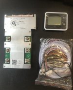
received the BMS last week 👍
380a continuous 950a peak.

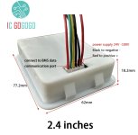
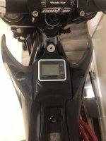
0EF17200-11BC-4217-BE6F-D8EA1042E823.jpegI’m not even sure if I can use this display because it needs 24v to 100v to power the unit. How can I use this display without using another step down? Or maybe that’s the only way is another step down. If so, I probably won’t use it. The main reason for even using this BMS display is just to see the voltage, although it’ll be convenient to be able to Monitor the different parallel groups.
 
Does the BMS generate and output the power it needs?

If not, you can always just keep the display at the charging station, plugged into an electrically-isolated wall adapter of the correct voltage, and connect it to the battery when needed to monitor things. If it's a cabled connection, I'd take the cable it comes with and cut it in half, then wire the BMS side to some waterproof connector you can mount in a convenient spot (like next to the charger plug). Wire the display side to whatever connector type is convenient, and make a cable from that to the WP type...or just wire that WP type to a long enough cable to wire into the display and reach the bike from it's mounting location (wall, etc).

Another option is install it all on the bike except the power for it, and then add two wires to your charger cable with a connector for the display power input, that then is powered by a wall adapter. Then you can see the state of the pack as you charge, even if not while riding.
 
Oh nice! So we can actually put a delay on the 12v aux output?? That sounds great to have the pre-charge connected to the ignition through a relay and then put a delay for the main Contactor to close.

What relay did you use for the pre-charge? I think you’re running similar voltage what size resistor did you use?
The aux is a ground that you can choose when you want it to turn on/off. It is common to both high voltage and 12v, so it can be used on iether I suppose. (but I used it on the 12v output) What Im trying to say is just that the 12v is not aux, and the aux is not 12v. But they can be combined ;) I dont remember what relay I used, but it is probably in my yamaha thread. Someting with about 110v coil. I use 30ohm resistors from vw passat gte.
 
Have you talked to the manufacturer about this ? Does it also have Bluetooth and it can be monitored from your phone. The most that interest s me parallel group cell level voltage.
 
Have you talked to the manufacturer about this ? Does it also have Bluetooth and it can be monitored from your phone. The most that interest s me parallel group cell level voltage.

Well, I messaged Hackey but never heard back. He’s normally pretty responsive. But from what j bjork is saying, looks like I can use the step down from the controller to activate the coil contactor.

Yes, there’s built-in Bluetooth with this model. Looks like most of the ANT BMS are Bluetooth from what I’ve seen.
 
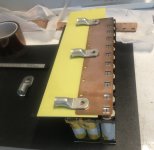
So I’ve been figuring out the best solution for my discharge wires coming from the discharge busbars. Space is very limited, especially on the bottom side where the negative discharge is. I won’t be using any solder and plan to bolt lugs directly to the busbars for less resistance, In theory at least 😅

So as of now plan to run three 1/0awg wires coming from the busbars. These three 1/0awg wires will be crimped into one large lug coming off the busbar. Then that will bolt directly to the 4/0 AWG main discharge wire.
What is your thoughts on this?
If I only use one lug connected to the busbar in one spot, it’s going to heat up the busbar so I’m thinking three 1/0 AWG wires would be more than enough for the current I will be using… trying to bolt the 4/0awg directly to the bus bar won’t fit due to space limitation, so I figured using multiple thinner wires would work better.


7AB7DBAA-E6C7-4CFC-B9CE-E30A9A067E66.jpeg

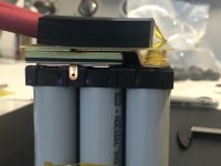
For insulation there’s two pieces of 1.0mm FR4 board sandwiched with 1.5mm dense rubber between the two boards.
 
4/0 seems big times 3.
LFP had a conductive cream formula. Plus he has some pretty serious battery knowledge. Past threads.
Do you plan on using a conductive Paste between the bus far and the lug ? When I use copper and other metals together on a battery down by the beach I can see some green crust probably activated by the conducted ability between two dissimilar metals. I guess if it happens it would show up over time and environment has something to do with it.

Maybe you have a different angle using this 4/0 as a heat sink to draw heat away from one end of the battery. I guess it was funny in my brain
 
Last edited:
4/0 seems big times 3.

It’s not 3 times 4/0 wire.. It’s 3 times 1/0awg off the busbar crimped into one lug. Then that bolts to the 4/0 main discharge wire.
LFP had a conductive cream formula. Plus he has some pretty serious battery knowledge. Past threads.
Do you plan on using a conductive Paste between the bus far and the lug ?

Wasn’t planning on it, but will consider.
Maybe you have a different angle using this 4/0 as a heat sink to draw heat away from one end of the battery. I guess it was funny in my brain

Im using 4/0 to achieve lower resistance and better efficiency. Also, considering this battery can max output 495amps it’s not that much of a stretch to use 4/0awg.
 
Yeah one out will be a lot easier to been up in your case to get it up to the controller. This is a monster of a battery that has needed a lot of planning.
As you want to use all your space for battery then you got to fit in wires BMS etc. I have cardboard mockups in the corner of my garage.
I got a new 3,000w hub motor and the phase wires are 5 and 1/2 ft long and two and a half feet long of resistance and I only need three feet or else the connectors can overheat. So I get it. More direct or shorter the better.
Good luck.
 
Last edited:
@harrisonpatm
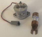
So I ended up ordering the coil contactor 👍
I bought the fuse as well since it was cheap, but not sure if I even need the fuse since I’m using a BMS?

I’m not ready to install it yet, still working on the battery tho… 😅😅😅
View attachment 339272
Excellent, I got two at some point months ago and have tested them in multiple different projects. My style of building is just slowly collecting components, spares and extra parts, then cobbling something together without ordering much new. I got my contactors months before I even started my next project.

Fuse is whatever works for your setup, I don't know what you're planning, but some kind of safety needs to be in place.
 
I bought the fuse as well since it was cheap, but not sure if I even need the fuse since I’m using a BMS?

A fuse is there to prevent current flow into a short circuit somewhere in the load past the point it is installed.

The BMS is there to prevent overdischarge, overcharge, or other out-of-limits conditions for the cells.

If the BMS can detect overcurrent and shut off it's output safely under a full short circuit condition, then it sort of does the same thing the fuse does, after whatever processing delay it has, assuming it's MCU hasn't crashed...but the fuse is designed specifically to do this, and you can pick fuses that will "instantly" blow under a short, or blow only after a certain amount of time, etc.

Fuses will have a chart from the manufacturer that specify their trip time for various currents (because they don't just blow at their rated current), so before using a fuse in an application it's safer to check the chart to be sure it can handle any current surges your system will *normally* have, but that it would blow quickly in the event of a short or other failure that causes higher current than your wiring, etc can tolerate. (so you don't have a fire).

EDIT: This is the chart for that fuse
 
Last edited:
Well, guess I will add a DC to DC step down to 24v since I need it for the BMS display, also can control the contactor through this as well. I don’t know why ANT BMS didn’t make the display able to run of 12v, would’ve just used the step down that’s built in the controller 🙄


Progress of lately has been to a crawl on the battery build but getting there. The negative discharge wires coming out the battery case need to be very exact because of clearance and waterproofing. I pretty much got it figured out now, I’ve tried a few different ways, with the wires coming through the battery case. Hopefully I can get this part finished soon and start stacking the cell blocks together. Still have to make some bends in the connecting busbars between the cell blocks which needs to be exact as well.

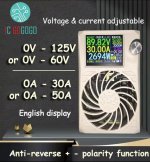
What do you all think about a charger like this? It can also be used as a regular power supply as the voltage and current is adjustable. Seller on AliExpress recommended this charger, I’ve bought several stuff from them.


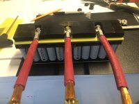
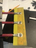
Here’s a pic of the bottom cell block, which contain the three 1/0 AWG discharge wires that will connect/bolt to the main 4/0awg discharge wire. That rubber block is actually the very bottom of the battery and will sit in the case on that rubber block. There’s no pressure on the discharge wires or lugs as you can see the rubber is notched. Most of the weight of the battery will be sitting on top of the motor, which will have a similar set up with a rubber block inside the battery case.
5AC473AA-8A0C-4C00-81DC-35083BE00930.jpeg
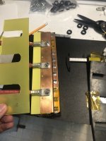
Will be stripping that red insulation off and using marine grade heat shrink. These three discharge wires will go through rubber grommets through the case, will use high temp silicone as well to make sure everything is 100% waterproof. I haven’t made this permanent yet. The discharge busbar is just taped into place as I need to get this very exact. I have spent many hours on this bottom cell block figuring out the most efficient way. The rubber block is just held on with tape as well, but will be using DP 420 to adhere that rubber block so it doesn’t move around.


B7AE2CD2-C509-42C8-B699-D7C7BEFD8AC1.jpeg
Many Layers of insulation between those two busbars. Had to do it this way to be able to create a notch for the bolts for the lugs.

EAB0C01F-CA74-4E49-96F3-7C2B96ECBCFD.jpeg0884E0C0-6CBD-4531-99F2-4993D33C5577.jpeg
Will use the DP420 of the lug bolts to keep them from coming loose. I use the dp420 inside my hub motors it can handle lots of heat.
 
Man, keep going slow and steady on the battery build, no rush, because the results are quality!

Well, guess I will add a DC to DC step down to 24v since I need it for the BMS display, also can control the contactor through this as well. I don’t know why ANT BMS didn’t make the display able to run of 12v, would’ve just used the step down that’s built in the controller 🙄

https://a.aliexpress.com/_mLRJCgQ
I have two stupid suggestions. First, do you have the display, already? If so, have you bench tested it to see whether it would actually power up with 12V? Because I agree that a component that needs 24v to run is a bit abnormal, and it might be able to run off a voltage range that includes 12v. It's pretty safe to test it on 12v without worrying about damaging it.

Barring that, here's my second stupid idea. I'm assuming that if the display does indeed need 24v to run, I bet it doesn't need much current (again, you can bench test it to confirm how much). If I had to guess, I'd say less than 500ma. If so, instead of a bulky, second, $30 step-down just to power it, you could probably step up from the 12v converter output with a small DC/DC boost module. Quick search here, but I've used several different small step-up modules in projects before, and if it's just running the display, nothing critical, you can buy 2 different ones and have a backup ready if the first one fails. I'm calling it a stupid suggestion because it does indeed seem counterintuitive to step voltage down from 120 to 12, then back up to 24, but in this case, with low current draw. it might be worth it for the size, cost, and weight constraints. You could always switch the input, turn the display on and off to keep the boost module from running 24/7.
 
Man, keep going slow and steady on the battery build, no rush, because the results are quality!

Thanks! Some days feel like I’m running in place and not moving forward 😅
Once I get past this bottom cell block with the negative discharge wires should start coming together.

I have two stupid suggestions. First, do you have the display, already? If so, have you bench tested it to see whether it would actually power up with 12V? Because I agree that a component that needs 24v to run is a bit abnormal, and it might be able to run off a voltage range that includes 12v. It's pretty safe to test it on 12v without worrying about damaging it.

Yes I have the display. The seller confirmed 12v is not enough. He mentioned that some other buyer already tried. the display normally connects directly to the battery, but it only goes from 24v to 100v.

206684C7-9E41-472C-A54F-8948E6F30ED7.jpeg
E830FD99-370D-4803-87FC-1C9B7F8DC87F.jpeg
The display is not installed yet, It’s just sitting up there.


Barring that, here's my second stupid idea. I'm assuming that if the display does indeed need 24v to run, I bet it doesn't need much current (again, you can bench test it to confirm how much). If I had to guess, I'd say less than 500ma. If so, instead of a bulky, second, $30 step-down just to power it, you could probably step up from the 12v converter output with a small DC/DC boost module. Quick search here, but I've used several different small step-up modules in projects before, and if it's just running the display, nothing critical, you can buy 2 different ones and have a backup ready if the first one fails. I'm calling it a stupid suggestion because it does indeed seem counterintuitive to step voltage down from 120 to 12, then back up to 24, but in this case, with low current draw. it might be worth it for the size, cost, and weight constraints. You could always switch the input, turn the display on and off to keep the boost module from running 24/7.

Yeah I already ordered the step down. Plus it’ll be convenient having a 12v power supply from the controller and then also having a 24v power supply, leaves me with of options for accessories. Although most things run off 12v.
 
What do you all think about a charger like this? It can also be used as a regular power supply as the voltage and current is adjustable. Seller on AliExpress recommended this charger, I’ve bought several stuff from them.


Does anyone have opinions on this charger?

it’s a bit pricey, but I haven’t found to many good options for a higher voltage battery like this 28S.
 
Two HLG-600H-54A in series should do it. (that's how the previous owner of the four I have used them--2s2p for about 24A of charging at around 116v, IIRC.

I'm only using them singly (one built into SB Cruiser), but since I'm using two packs in series on the formerly-corded AC lawnmower I keep thinking I should wire up a pair in series again to charge it, instead of charging each half separately with just one. (laziness)

The nice thing is they're completely potted and sealed; the one on the bottom of SB Cruiser has been submerged at least twice in flash flood waters on the way home from work, and wetted during rains many times.

Like that PSU, they're not really chargers, just CC/CV devices, so to use them as a set-and-forget charger it'd be a good idea to also use a device between them and the pack that shuts off current once it drops below a certain amount (whatever you see when the pack is "full"). I don't have one of these, but I keep thinking about getting one, if I could ever remember what thye're called when I am looking around for handy little bits and bobs I could get.
 
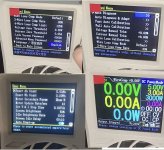
Well pulled the trigger on this charger. It has lots of settings and different functions than a normal charger. Since the voltage and current is adjustable, I can use this for different ebike batteries. But yeah, I didn’t plan on spending this much on a dang charger 😅


77EEAE22-5167-4C88-AD3B-DEDD0DE72922.jpegA9BC4506-293D-4AB5-938A-28B1E96EE401.jpeg
 
I think this unit or one very like it was used in another thread here...lemme see...found it
 
Back
Top