Been a while, but I've got some updates to share. I found a home for the controller. I will mount it in the subframe. It fits nicely and can get decent airflow if I mount a heat sink on it. The only down side is that the motor phase wire will not reach it so I plan to make a small junction box. I know it's not optimal, but the overall cable lengths won't be that much longer. I thought about mounting it under the batteries but it reduces lean angle clearance and mounting is tricky. Also in a crash it is less protected  Here are some photos.
View attachment 17
View attachment 16
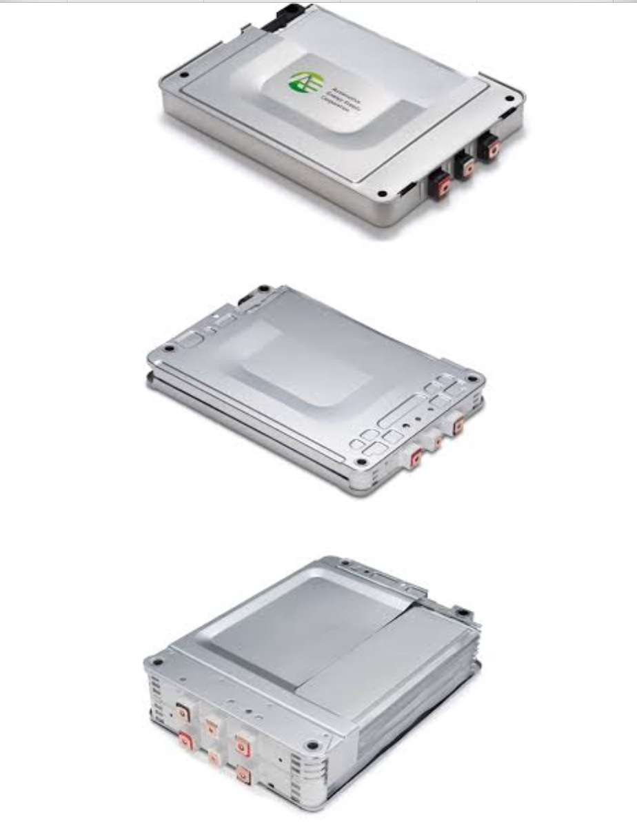
I started charging the modules one by one with a lab power supply. For now that's my method until I decide on a charger. I charged each cell to 3.8V. The idea is to keep them around nominal voltage while I setup the Sevcon and configure the motor.
View attachment 2
Then I assembled my two battery packs. The first one is 9 modules and will be mounted in the main area of the frame where the engine used to be. The second one has 5 modules and will be mounted on top of the steel tube frame and will be inside the perimeter of the original Buell frame. So overall I like that everything will be well protected.


View attachment 15
View attachment 4
Saftey first! :wink:
View attachment 3
Next I took the stock wire harness from the Buell and tore it apart to get some free wires out of it.
View attachment 1
I ordered a bunch of connectors, terminals, etc from Mouser to wire up everything and start the configuration of the Sevcon.
Here is the super special old IXXAT USB-CAN compact cable that works with the old DVT software. Cost me ~$350 I bought a Sub D9 connector and soldered the CAN High, CAN Low, and GND connections on it. You also have to solder on a jumper wire from pin 2 to pin 24 on the Sevcon for the CAN termination if this is your only controller/CAN device.

Here are some pictures of my bench top setup. I screwed down the controller, contactor, and a SS relay that I bought to switch the high-voltage on. For now I am providing the 12V power through my lab power supply, but in the final design I will use a DC-DC with the enable switch. The relay has a nice green led to indicate when 12V is applied on the input side.
View attachment 13
You can see the SS relay here on the right
View attachment 12


View attachment 9
My battery cables are quite long, but I will shorten them when everything is finalized.

View attachment 7
So far my wiring diagram seems to be correct.The first power up was successful. I got the contactor to close once I flipped the on/off switch on the handle bar and closed the SS relay. FYI I'm using a 48V coil contactor based on what I read about the Sevcon not liking 12V/24V coils, since it PWMs the contactor.
Now I have to setup the CAN interface on my computer and start talking with the Sevcon so that I can set up the initial parameters like the contactor PWM voltage. More to come soon hopefully.
Here are some photos. View attachment 17
View attachment 16
I started charging the modules one by one with a lab power supply. For now that's my method until I decide on a charger. I charged each cell to 3.8V. The idea is to keep them around nominal voltage while I setup the Sevcon and configure the motor.
View attachment 2
Then I assembled my two battery packs. The first one is 9 modules and will be mounted in the main area of the frame where the engine used to be. The second one has 5 modules and will be mounted on top of the steel tube frame and will be inside the perimeter of the original Buell frame. So overall I like that everything will be well protected.
View attachment 15
View attachment 4
Saftey first! :wink:
View attachment 3
Next I took the stock wire harness from the Buell and tore it apart to get some free wires out of it.
View attachment 1
I ordered a bunch of connectors, terminals, etc from Mouser to wire up everything and start the configuration of the Sevcon.
Here is the super special old IXXAT USB-CAN compact cable that works with the old DVT software. Cost me ~$350
Here are some pictures of my bench top setup. I screwed down the controller, contactor, and a SS relay that I bought to switch the high-voltage on. For now I am providing the 12V power through my lab power supply, but in the final design I will use a DC-DC with the enable switch. The relay has a nice green led to indicate when 12V is applied on the input side.
View attachment 13
You can see the SS relay here on the right
View attachment 12
View attachment 9
My battery cables are quite long, but I will shorten them when everything is finalized.
View attachment 7
So far my wiring diagram seems to be correct.The first power up was successful. I got the contactor to close once I flipped the on/off switch on the handle bar and closed the SS relay. FYI I'm using a 48V coil contactor based on what I read about the Sevcon not liking 12V/24V coils, since it PWMs the contactor.
Now I have to setup the CAN interface on my computer and start talking with the Sevcon so that I can set up the initial parameters like the contactor PWM voltage. More to come soon hopefully.