EMC-1000 900w Charger FAQ Info from BMS Battery

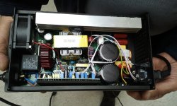
the trimpot on the end adjusts the voltage. set it to 63+ volts for 17S lifepo4. measure between the output of the schottky diodes and the wire loop of the current sensing shunt.
 
Thanks Dnum, I marked in red what I understood for the schottky diode and voltage adjustment:
2013-08-05%2023.25.20.fw.png


Not sure where is the current sensing shunt?
 
I should make up some cheap inrush current limiter boards for these.

I've got a good design that actually bypasses the NTC when the caps are charged. I need to get one or two and see what they use inside. If its something like a UC3805/5 then just pulling pin 1 to ground would shut off the oscillator.


I'm thinking these may use a current mode controller (finally!!) due to the current transformer I spotted in there.
 
the schottky diodes are hidden under the heat sink on the side. that trimpot is the one to adjust the voltage.

i think that charger has a big ICL already. it is about 25mm diameter so i suspect it can handle about 12-15A. they actually solder one leg into the spot on the pcb where the line would normally be soldered into the board and the other leg of the ICL is soldered to the line as it comes from the fuse. almost as though installing the ICL was an afterthought.

on all the others they have a place for the ICL but none present, just a jumper.
 
Sounds like an afterthought.

Leaving them in-circuit all the time is wasteful - they run hot, especially on a 900W rated charger.

Also - do you know the control IC used on these? I see a current transformer, but not sure if it is primary or secondary side. Primary would indicate current mode control, secondary would be voltage mode (most likely).
 
Can somebody help me to config the charge wires. There is a brown and a blue wire - which one is for Batt + (plus) and which one is for batt. - (negative)?

Thanks
Mic

Edit:
Did find it thank you! :)
 
Today I opened the CB EMC1000, I need to tune the voltage bringing it from 72V to 82V. Unfortunately it seem impossible to raise the voltage beyond the 77V :-( I read the previous post and see the comment on "how to raise the voltage" using the W503 pot in combination with W4011...

<<
5 = W4011 ; turn CCW to increase V_out ; shifts the range of W503, kind of offset?; I tried W503 ranges for a number of fixed W4011 positions e.g. 47.0-105.7V, 42.5 - 96.0, 32.5 - 73.5, 28.0 -63.5; I was able to trim down V_out minimum to 2V!
>>

The CB look slightly different from what has been posted ate the begin of this thread, below the picture of my CB
Please someone could suggest me how to raise the Voltage?

Thank you in advance
 

Attachments

  • 2014-05-29 08.53.03.jpg
    2014-05-29 08.53.03.jpg
    124.7 KB · Views: 2,257
Does anyone know why is my charger taking only 450W from socket when charging? I have adjusted the voltage to 73,8V and both current settings are at max position. When it was new it was much faster so it was taking more current. Before adjustments it was taking only 300W from socket. How can the settings change by itself?
 
not sure what you meant about the two adjustments for max current. i do not think that is selectable on this type of charger design. do you have some instructions or directions to indicate that the max current is adjustable?
 
The current can be changed from trimpot W401 and W402, see first page. Have you measured how much is yours draining from socket?
 
I have actually 3 models: emc-1000, emc-400 and emc-240. I have problems at least with the 2 first mentioned, the last one I haven't even tested.
 
Any experience with EMC-1200?
I'm coming into a large supply tuned to 12s 18 amps.
I will need to learn how to re-tune and find upper and lower limits. Hoping to blow them out as 12v automotive chargers if need be.
Good experience with 36pcs EMC-240 4.2v 10amp. Only minor issues. A few left. Tunes up to about 8v.
 
My buddy got two chargers with his Elf. One is slow charge @ 3 amps nominal 49V for 16S Headway pack max out 58v and change
This charger works find and charges this pack and comes on when I connect it to my 14S Li-ion with Panasonic 18650 cells all fine.
The other charger however.... is an EMC-1000 set for LiFePO4 48V nominal at 15 amps. This charger will not come on period.....
since new. I have connected it to multiple packs with start charge V at 48-52V No LED activity no output NOTHING.
It does spark (Just a Bit) when the 120 VAC is plugged in. Can anyone tell me how to check output "PRE RELAY" ? is it possible?
I have cover off but have not De-bonded it from the case yet to check under the board. All up top looks ok...
Any help.... mine looks just like the one pictured by ccriss with the 6 pots visible but my trans says YC4815-T
Again any help....P.S. yes I checked the fuse
Thanks
 
The EMC-1200 might be similar.
Are there two transformers?
If no lights, then the control smps is not running. There are two. One for control and one for charging power.
Should be a to-220 mosfet near the small transformer.
Check for short between pins.
Look for low ohms resistor (~1ohm) open.
8p dip is smps controller. Possibly 3842.
Sparking shows buss caps charging. Softs start slots not populated in mine. :(
Switch turns on control smps circuit. Two small wires to near small transformer.

Not sure how much of this carries over to smaller chargers.

I'm in the middle of a doa repair of one of my 12s EMC-1200s.
Bad mosfet, 1 ohm, 10k ohm, gate diode,3842, so far.
 
I have the same charger and it broke after charging my 20ah pack 17 times. When I plug it in the lights don't come on and it won't charge. Does anyone know how you can fix these chargers? I took it apart and nothing looks burnt and I can't find any fuses.
 
Mine have a fuse in the input module. Poor inrush protection. Common to blow input fuse. Very repairable. Common parts.
Check for high voltage on main buss caps. Check enable switch in power input module if it has one.
 
info from manufacturer:
2s.jpg
 
Back
Top