Even Newer 4 to 24-cell Battery Management System (BMS)

Ok, I am not sure if this is good forum etiquette or not, but there ARE 80 pages of it ;)

I know its in here somewhere, but for this potential customer, is it working, will it do 24 100ah lifepo cells, and how much is it?
Thanks
 
Yes, this is getting a bit long. Maybe we'll start a new on, with more info in the first post.

Anyway, the board is about $50 and for a 24-channel version the parts will run you another $80-$85 I think. the rest is just your labor. :mrgreen:

There's no problem using this board with a 24s 100Ah pack, but if the cells are typically out-of-balance than about 2-3%, it could take 6-8 hours to balance, with the 6.8 ohm shunt resistors, which limits the balance current to about 500 mA. These can be replaced with 3.9 ohm 5W resistors, which will double the shunt current, but the board would need a heatsink for the resistors and a fan.

-- Gary
 
i would like for richard to go back and edit it so that just the important posts are collected into a stream, maybe he could edit what happened at each section of the evolution of the design, then put it on archive in the technical section. or maybe make it a little like a wiki for those few involved to make comments, all the other chatter could leave. some of it i am not proud of has already been deleted. maybe not enuff.

that should get it under 5 pages.

thanks for everything you guys, duane may sell me one of his v2.2 boards so i may build one yet.
 
I suspect I am not alone in wondering this...

Can I pay you Richard, or someone else on this thread to "whip me up" a solution, plug and play?
What would something like that be worth?
 
dnmun said:
i would like for richard to go back and edit it so that just the important posts are collected into a stream, maybe he could edit what happened at each section of the evolution of the design, then put it on archive in the technical section. or maybe make it a little like a wiki for those few involved to make comments, all the other chatter could leave. some of it i am not proud of has already been deleted. maybe not enuff.

that should get it under 5 pages.

thanks for everything you guys, duane may sell me one of his v2.2 boards so i may build one yet.

Yes, I would like to do this, but it is a very time consuming process. It's on the to-do list.

We are also working with a manufacturer to make fully built units (surface mount). This will take a while, but we hope to be able to offer fully built units in the near future. For now, it is way too time-consuming for me to build them. Perhaps someone else out there may offer an assembly service.
 
Have you considered making a "high voltage" version? I am looking at building this for 112s5p A123 pack or at least giving some hints on what needs to be changed in the design to go to higher voltages?
 
I have a couple questions/issues.

I've noticed with my BMS, that I need to turn up the voltage on my chargers to about 60.5v to get them to fully trip the main LED green to turn off after balancing.

On many ocassions, the individual channels light up fully, and the cells appear to be balanced, but the main LED won't trip. Thus, the BMS resistors keeps bypassing for an hour or so.

Even with the voltage turned up, it can take up to an hour to trip.

I wonder if it is the lower amp rate (2a) of my charger that is the problem?

Or, maybe the circuit is getting too hot in the enclosure I built. It gets warm, but not super hot, as the board is sideways with the big resistors mounted up to let the heat rise out of the enclosure.?
 
Gary, please correct the BOM error on the tppacks website.. the 10 uF and the 1uf qty and type are not correct!

I now have 72x 10uF caps for the 3 BMS... and i should need only 6.. but these 10uF are non polarized type and the C1 and C2 are polarized...

And the 1uF.. I should have 72 of it.. and i have... zero..

Maybe i'm wrong.. but one conponents is missing and i have too much 10uF.. 35$ of little 10uf caps.. and i need just 6..

I used the online BOM

-And Q4 is named twice times.. : for the STP160N75 mosfet .. Q4 seems an error if designing the STP160...
cause it is the Q2 ( STP160N75)

-and for the KPS44 PNP transistor , i think it should be Q3 on the schematics..

-and.... :? on the PCB this time... Q2 label is at the location for a to-92 transistor.. it should be named Q3 i think... again...Q2 is the large TO-220 mosfet according to the schematic..

-and.. on thge PCB, Q3 should be labeled Q4 according to the schematic....

Thanks God to still have not put any power on it!! :roll: :shock:


Two 24s BMS assembly in ONE evening is... just... isane! :? :x :p :| :oops: :shock: :shock: :?: :!: :arrow:


I need coffe!

Doc
 
Doc --

I will check the lists and the schematics in the morning. In any case, the 10uFs will work fine. Richard changed to a 1uF I think mainly because it is cheaper.

-- Gary
 
Yes, you can use either 10uf or 1uf on the cell circuits. I doesn't seem to make much difference in operation. The 1uf are significantly less expensive however. We'll try to get the BOM files corrected.

I'll check on the transistor numbering...
 
Yes, Doc, I see what you are talking about. There are several mistakes we need to clean up.

Most are in the parts list, which we can fix easily. As far as the mistakes on the board layout labels, it might be easier if we change the schematic to match the board somehow. I guess we would make the FET into Q4 and relabel accordingly.

Thanks for pointing this out, as the thing is pretty complex and we tend to miss something on each pass.
 
The BOM files have been corrected. I had inadvertantly used the same part number for both the 1uF and 10uF parts, but like Richard says, it wont matter which one you use. The previous version all used a 10uF electrolytic.

We've updated the schematic file to match the PCB layout. It is included in the updated instructions which can be found here. The FET is Q4 and the two transistors in the 12V regulator circuit are now Q2 and Q3, just like in the PCB layout.

Sorry about the confusion. With a "profit" of about $10 per board, it is hard to get good help around here. :roll: :mrgreen:

-- Gary
 
Thanks for the confirmation for the update Fechter/Gary! :wink:

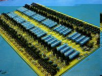
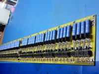
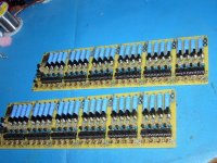
Yesterday I just completed the assembly of those two V2.5 24s BMS in 7 hours non stop!

A great way to make man turning into real ZOMBIE !
:shock:

But it worth... the results is just perfect!!
I need not to test it and make a final visual inspection before connecting to the drag battery!.. i'll use 2 x 14s in serie for loading and in parallel to recharge the pack ( the pack is divised in two 14s pack).. so i'll parallel charge them.. but each pack will have it's own BMS


here is some pics of what wold look like a 48s dual BMS :twisted:
 

Attachments

  • P1070680_800x600.jpg
    P1070680_800x600.jpg
    116.7 KB · Views: 2,180
  • P1070681_800x600.jpg
    P1070681_800x600.jpg
    94.7 KB · Views: 2,179
  • P1070683_800x600.jpg
    P1070683_800x600.jpg
    118.9 KB · Views: 2,181
i dont know his reason but the gate driver is static sensitive and possible heat sensitive and my guess is the socket makes for minimum time between the protection of the anti static foam block to the board and keeps the heat off since you dont have to solder it.

also it makes replacement easier too if it should fail.

the anti static foam block is made of a material that conducts electric and acts in the same way as taking some wire and shorting all the pins together.

while most of today's semiconductors are probably not going to be harmed because of internal protections it is never a good idea to leave parts like that unprotected any longer than required for assembly.


webfootguy said:
Doc,

Any particular reason you used sockets instead of soldering the parts directly in? Is that reliable enough?
 
@fechter/goodrum

is there any intention for you to design a separate charger controller for those who have blank bms segments left so they can make another complete functional bms?

when i built mine i have 2 segments (8 channels) left and it would be nice if we could be able to buy just the charger controller segment so we can connect to the remaining unused segments so for me for example i could make a complete 8 cell bms.
 
ejonesss said:
@fechter/goodrum

is there any intention for you to design a separate charger controller for those who have blank bms segments left so they can make another complete functional bms?

when i built mine i have 2 segments (8 channels) left and it would be nice if we could be able to buy just the charger controller segment so we can connect to the remaining unused segments so for me for example i could make a complete 8 cell bms.


Great Question!

Doc
 
Patriot said:
I have a couple questions/issues.

I've noticed with my BMS, that I need to turn up the voltage on my chargers to about 60.5v to get them to fully trip the main LED green to turn off after balancing.

On many ocassions, the individual channels light up fully, and the cells appear to be balanced, but the main LED won't trip. Thus, the BMS resistors keeps bypassing for an hour or so.

Even with the voltage turned up, it can take up to an hour to trip.

I wonder if it is the lower amp rate (2a) of my charger that is the problem?

Or, maybe the circuit is getting too hot in the enclosure I built. It gets warm, but not super hot, as the board is sideways with the big resistors mounted up to let the heat rise out of the enclosure.?

The charger needs to supply over 1/2 amp (or whatever the shunt current is) at the peak charging voltage in order for the auto shutoff to trip. The BMS circuit will regulate the voltage, so the charger can be cranked up way over the minimum voltage without damaging anything. If your charge current tapers off too much toward the end point, it might not have enough current to trip the auto shutoff.

You can test by measuring the charging current with an ammeter.

The voltage set points may change slightly with temperature, so this could be part of it.

On a similar note, Nate sent me his board after trying to troubleshoot remotely for quite a while. I found that everything was working properly, but the red/green LED is difficult to read. When it is slightly green (according to the signals going to it), it still appears solid red to the eye. I guess this can be real confusing. In the future we may recommend a water clear version or separate red and green LEDs to make it easier to read.

Also the voltage settings on all the cells are slightly higher then I was expecting based on past builds. His board is averaging 3.7v +/- .02v per cell, which should be just fine for the batteries, but in the past I've gotten closer to 3.68v. Not a big deal, but I may consider changing the divider resistor to bring it down a bit. This could be largely due to tolerance variations in the resistors or the LM431's.
 
ejonesss said:
@fechter/goodrum

is there any intention for you to design a separate charger controller for those who have blank bms segments left so they can make another complete functional bms?

when i built mine i have 2 segments (8 channels) left and it would be nice if we could be able to buy just the charger controller segment so we can connect to the remaining unused segments so for me for example i could make a complete 8 cell bms.

Yes we have considered that. If there was enough demand we could do a shorter board. I think at least 4-8 cells with a control circuit.

Plan B is to sell your sawed-off sections to guys that want to add on to existing boards.

Also: I don't really recommend using sockets for anything. They tend to fail over time, especially if it is a high current path.
 
Doctorbass said:
Thanks for the confirmation for the update Fechter/Gary! :wink:

Yesterday I just completed the assembly of those two V2.5 24s BMS in 7 hours non stop!

A great way to make man turning into real ZOMBIE !
:shock:
....
here is some pics of what wold look like a 48s dual BMS :twisted:

Nice work Doc! That's some real BMS porn.
I think you're the first one to do a version 2.5 board. I don't even have my parts yet.

How was the parts fit? I tried to leave more room for the resistor leads so they fit better.
I like the MLCCs over the aluminum electrolytics. They should be much more vibration resistant.
 
fechter said:
Also the voltage settings on all the cells are slightly higher then I was expecting based on past builds. His board is averaging 3.7v +/- .02v per cell, which should be just fine for the batteries, but in the past I've gotten closer to 3.68v.

Yes, I also found that the cells that charge up first can overshoot slightly, reaching 3.80V or even a touch higher, then settling back to around 3.74V after a couple of minutes while they wait for the others to catch up. I'm thinking about changing the divider resistor to bring the voltage down a touch, as I don't like holding the Lifebatt cells over 3.7V for long. The Lifebatt charger was originally set for 3.65V per cell. If the same cells reach full charge first on a regular basis they could possibly be stressed by this slight, but frequent, overcharging. I'd rather undercharge slightly to ensure long life.
 
i have the software to design circuits i guess i could copy the charge control section using the schematic and send you the source files or have them made my self and start selling charge controllers.


fechter said:
ejonesss said:
@fechter/goodrum

is there any intention for you to design a separate charger controller for those who have blank bms segments left so they can make another complete functional bms?

when i built mine i have 2 segments (8 channels) left and it would be nice if we could be able to buy just the charger controller segment so we can connect to the remaining unused segments so for me for example i could make a complete 8 cell bms.

Yes we have considered that. If there was enough demand we could do a shorter board. I think at least 4-8 cells with a control circuit.

Plan B is to sell your sawed-off sections to guys that want to add on to existing boards.

Also: I don't really recommend using sockets for anything. They tend to fail over time, especially if it is a high current path.
 
My two 14s(partial 24s) BMS are tested and 100% functional :wink:

now it's time to connect to the battery... but i just wonder... What is the continuous charging current max that the STP160N75 FET can take ?

according to the SOA curve, if i charge at 51.8V CC-CV, the max current posisble is 9A at 10ms pulse :(

But i want 20-30A charge... :?:

any suggestion.. data?

Doc
 

Attachments

  • STP160N75.JPG
    88.4 KB · Views: 1,299
The limitation on the STP160N75 will be the heat generated due to the resistance. I estimated around 20 amps it will start getting toasty warm. You can add a heat sink to increase the current. You also could have used IRFB4110's for that part. The new board layout has in increased surface area for the heat sink under the FET, so it might handle 30 amps without getting too hot.

Try running it at 20A first and carefully watch the temperature of the FET. The charge current will taper off after a while, which will reduce heating.
 
Back
Top