Even Newer 4 to 24-cell Battery Management System (BMS)

OK, I checked the large resistor legs on the far end where they connect to the board, right next to the channel lead connections. Here's the voltages I got between them.

1-2 - 3.35v
2-3 - 0.00v
3-4 - 1.82v

5-6 - 3.35v
6-7 - 0.00v
7-8 - 1.83v

So, the voltages appeared to have the same pattern between the two banks.

I also checked the channel leads at the point of contact on the board. They all read 3.35v.

Just got home from the night shift. I'm off to bed. I'll be back this afternoon.
 
How many current this BMS consumes? Can I leave it connected to the pack for a week? My pack 20S5P A123. Divider made from 120 and 330kohm. Only divider consumes just 3.3V/450kohm=7.3uA. What about other elements?
 
Karolis said:
How many current this BMS consumes? Can I leave it connected to the pack for a week? My pack 20S5P A123. Divider made from 120 and 330kohm. Only divider consumes just 3.3V/450kohm=7.3uA. What about other elements?

It draws around 200uA total (measured). The LM431 eats most of it.
That will be no problem for a 5p pack for even months.
 
Patriot said:
OK, I checked the large resistor legs on the far end where they connect to the board, right next to the channel lead connections. Here's the voltages I got between them.

1-2 - 3.35v
2-3 - 0.00v
3-4 - 1.82v

5-6 - 3.35v
6-7 - 0.00v
7-8 - 1.83v

So, the voltages appeared to have the same pattern between the two banks.

I also checked the channel leads at the point of contact on the board. They all read 3.35v.

Just got home from the night shift. I'm off to bed. I'll be back this afternoon.

I meant to have you measure the end of the power resistor that is close to the edge of the board and connects directly to the cell tap wires. They should all be in the 3.3v range.

If the shunt is lighting up and the resistor is heating with only 3.35v going to it, there is a definite problem with the cell circuit.
 
^^^ Yes, I am reading 3.35v at the contact points of the big blue power resistors.

Also, when I connected the lead back up again, I actually measured 2.95v across the resistor itself. I even measured from the resistor to the LED and got about the same. So, current is flowing through the channel for some reason.

Could the shunt have activated and gotten "stuck", like you said?

If so, now what? And, which one is the shunt? How do I check that?
 
Hi fechter and others,

to keep the MOSFET cool, I tried to replace the original MOSFET by an IRF1324S type (VDss 24V, 1mOhm) in my 4 channel BMS.
http://www.irf.com/product-info/datasheets/data/irf1324s-7ppbf.pdf.

Now the main (bicolor) LED starts to light up if I just connect the battery (without power supply). What can be wrong ?
One thought would be that I burned the MOSFET while soldering as D-Pack is pretty nasty to solder, but I tried a second one
and got the same result. Is there any reason why this MOSFET should NOT work in the BMS ? The BMS is okay as soldering
back the original MOSFET let it work again.


Thank you very much,
Thomas
 
Patriot said:
Could the shunt have activated and gotten "stuck", like you said?

If so, now what? And, which one is the shunt? How do I check that?

Remove the LM431 or just lift the anode leg. If the shunt is still on, then it means the shunt transistor fried or has a short in the wiring. If it clears, then replace the LM431 and check the divider resistors.

You might be able to use the diode check function on a DVM to measure the shunt transistor in circuit (no power or cells attached). You can compare readings to a good channel. When testing with a DVM, swap the leads and measure each pair of legs both ways. A shorted one will measure near zero both ways from the emitter to the collector. I forget which transistors you have installed, but shunt transistor is the big one.
 
bapou said:
Now the main (bicolor) LED starts to light up if I just connect the battery (without power supply). What can be wrong ?
One thought would be that I burned the MOSFET while soldering as D-Pack is pretty nasty to solder, but I tried a second one
and got the same result. Is there any reason why this MOSFET should NOT work in the BMS ? The BMS is okay as soldering
back the original MOSFET let it work again.


Thank you very much,
Thomas

That's strange. I can't think of a reason why that FET would cause the problem you see and the original one doesn't. Let me think about it.
Edit: Look carefully at the pin diagram for your new FET. Only the single pin on the far left is the gate connection. If there was a connection from any other lead to the gate line, it could backfeed the red LED and make it come on.

Another way to get a lower Rds would be to stack several FETs in parallel. The gate driver is capable of running several in parallel. Technically, each parallel FET should have a separate gate resistor (100 ohm in this case). If you do the math, a 4A gate driver should be able to run something like 30 parallel devices with 100 ohm resistors. In real life, the voltage regulator won't handle that, but I'm sure you could run 4 parallel with no problem.
 
Patriot:
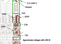
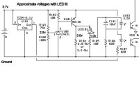
Here is a partial schematic and board layout for a single cell circuit.
If you apply power to a single cell circuit enough to light up the LED, the voltages should be close to those shown. If something is way off, it will give you a clue.

With your problem cell, you could try attaching a cell and measure the voltages.

Ideally, you'd want to test cell circuits with a current limited adjustable power supply. Set the current limit to less than the shunt current.

If you don't have a current limited power supply, a 120v, 40w incandescent light bulb in series with the charger output may work as a substitute.
2_3 Cell Circuit Test Points.jpg
2_3 Cell Circuit Schematic.jpg
 
Hi fechter,
thank you for your fast response. I connected the FET in the right way, (1 and 5 pins) so the only reason left is that I burned it during soldering.
To test it I will connect the next FET with wires first (so no danger of burning it) to see if this is the case.
Thomas
 
fechter,

I will connect it again and check all the voltages the way you show. I already know that I'm getting about 3v across the resistor when connected, and the led is lit. All the other cells do not have this, because their LED's are off, as they should be.


I'll also do as you recommend, and remove the LM431/ U102, and see what happens when I reconnect that cell to the battery. I'm hpoing it will not light up, and only LM431 needs replacing. If not, then I'll be back to bug you some more. :wink:
 
Before you start ripping parts out, try just measuring the 2.5v on that cell when the LED is lit. If you have over 2.5v, then the divider resistors must be messed up. If you see under 2.5v, then the LM431 is suspect. To test if the LM431 is shorted, you could try putting a 1k resistor from the 2.5v test point to ground. This should make the LED go out and turn the shunt off. If it does nothing, then the LM431 is probably toast.
 
Ok, I'll do that first. I'd prefer it, without having to pullout the LM431.
 
^^^^ Ok, I got some interesting results.

I used both my meters. The first was my cheap digital meter.

Digital
3.0v - 2.95v actual.
2.5v - 2.22v actual.
1.0v - 1.05v actual.

The second was my old tiny pocket analog meter. It can only give me a 0.1v accuracy using the 10v range setting.

Analog
3.0v - 2.9v actual.
2.5v - 1.5v actual. ????
1.0v - 1.0v actual.

So, both meters indicated a slightly lower reading at the 2.5v test point off LM431.

I have some 1k resistors, I'll try testing with one of those next.

^^^^ UPDATE:

Ok, I tried several times using a 1/4w 1Kohm resistor, connecting the GND to the 2.5v test point, and the LED stayed ON the whole time.
 
Patriot,

Double check the voltages around the 431 and BD136 for channel 7 and 9.

I did a repair on a damaged board and one strange symptom was that damage on channel 6 caused the orange LED to light on channel 7. Ended up replacing the TC54, LM431, and BD136 on three channels to bring it back to life.
 
Patriot said:
^^^^ UPDATE:

Ok, I tried several times using a 1/4w 1Kohm resistor, connecting the GND to the 2.5v test point, and the LED stayed ON the whole time.

That would indicate a blown LM431. I guess try changing that next.

I think if there is an accidental connection to something more than one cell, it can blow that thing instantly. In the future, I may consider adding a resistor to the circuit that could protect against that up to a point.
 
Hi

Just wanted to say thanks for the help this forum has provided for us in the completing of our BMS during our project in school. Can also provide with the tip to install a transil diode of the type SM6T6V8A between every channel. This decreases the risk of damaging components making the channel LEDs light at to low voltage, which has the solution:

I did a repair on a damaged board and one strange symptom was that damage on channel 6 caused the orange LED to light on channel 7. Ended up replacing the TC54, LM431, and BD136 on three channels to bring it back to life.

Anyway our project is finished now and you can watch the result att www.bikelith.st and hopefully get some inspiration.

Big thanks and keep up the good work!

//the BikeLiTH group
 
fechter,

I finally got around to ordering some spare parts today. I ordered 6 of each, LM431, TC54, and KSA931. AndyH said he replaced the BD136 for part Q101, but mine came with KSA931YTA originally, so I ordered that instead. I'm assuming it's the same thing.

I plasn n just changing out the LM431 to start with, and see if that fixes my pron\blem. If it doesn't, then I'll replace the rest in the channels surrounding each of any further problem channels I may have.
 
Good plan. The BD136 is bigger, but it will work fine if only some channels use them.

While you're waiting, you could remove the LM431 and verify the LED no longer lights up. If the LED still comes on after removing the '431, then it means Q101 is shorted. I don't think this is the case on your problem channel, otherwise the voltage across the shunt resistor would have been closer to the cell voltage.

BikeLiTH, yes the transorb is a good idea. If I add a resistor in series with the base on Q101, it should tolerate a breif exposure to much higher than design voltage and may prevent the kind of problems Patriot has run into. The transorb diodes are better for aborbing very fast transients, like you would get from inductance in the wires, etc. Both would be better yet.
 
Mouser parts showed up in the mail today.

Well, I installed a new LM431 on channels 7 & 8. After reconnecting, the LED still came on for channel 8. Being stupid, I didn't check it when LM431 was removed, so I can only assume it's the Q101?

What next?
 
OK, this is what I have done so far.

I replace these parts in the following channels.

Ch. 7- U102, Q101, and U101.

Ch. 8- U102 and Q101. Channel 8 now appears to be normal now.

I replaced all three parts in ch.7, and I am still not getting 2.5v at the U102 point. It only says 0.1v. So, I replaced it, twice (thinking I may have messed it up the first time), and still nothing.

This driving me nuts. Could this have something to do with the overvolting I was getting on ch.7 before when balancing?

Now what the heck do I do?
 
fechter,

Something just dawned on me. What if I have a bad cell?

I say this, because after hooking up the BMS with my new leads to the battery, I now see that my channel 7 and even channel 3 were extremely low. Both around 2.1v.

Well, out of pure contempt, I hooked up the charger, and turned it on. Most cells started heading up to the balancing point, and channels 3&7 came up to about 3.0v and kept charging while the others balanced.

It seemd to be balancing before. Why it's messed up now, I don't know. It could be bad cells, or maybe the bad channel connections were not fully charging those channels. I don't know.

So, I disconnected the charger for now.
____________________________________________________________

After disconnecting the charger, and cell channels have come up to about 2.95 volts for channel 3 & 7, I am now reading some voltages on the U102 test points. It's not 2.5v yet, but that because cells voltages are still low.

I wonder if in fact my BMS is ok, since now I'm reading voltages on my test points like one would expect.

It's just a couple cells that may be bad. I just don't have anymore time or money to dump into this thing. I think this is it for me. I'm on the verge of selling this baby. Matter of fact, I think I'll see if anyone who's about 6'0" in the forsale forum is interested. I may just sell the bike, which is all wired and runs beautifully, but just leave ou the battery for them to get themselves. Or, sell the whole thing for a song, for anyone who wants to replace the bad cells.
 
Hi all!

I have been planning to use this BMS on my car to control the charger, Still I have not come to the point where it does and I have fried one cell already.
Its a bit pricy at $200/piece. but fortunately i bought 2 spares.
Anyway here is my question:
Can I put a IDL2 in parallell with the 2-color diod? So that one colour of the diod will pull one of the optos, and the other colour will pull the other opto.
This way I can easily put a small relay on each of the optos. Any ideas on if it would work ?

Regards
/Per
 
Patriot said:
fechter,

Something just dawned on me. What if I have a bad cell?

I say this, because after hooking up the BMS with my new leads to the battery, I now see that my channel 7 and even channel 3 were extremely low. Both around 2.1v.

Well, out of pure contempt, I hooked up the charger, and turned it on. Most cells started heading up to the balancing point, and channels 3&7 came up to about 3.0v and kept charging while the others balanced.

A bad cell is certainly possible. I have one on my test pack that does something similar. All the other cells come up, but the bad one takes forever to get up to the trip point. If I let it cook long enough, it does finally come up. If I let the pack rest, the bad one drops faster than the others and gets below 2v in a few days.
 
Back
Top