Farfles Iron Horse build

very nice, cant wait to see it finished! got the battery boxes mounted yet?

the aluminium sheet stuff is used in building mainly. called aluminium composite panel, made from 2-6 mm thick and used as a fire resistant wallboard, they are a polyethelene plastic with aluminium covering and zinc paint. originaly made by a company called alucom, but since then china has started manufacturing them... i tested the stuff as a shock tower in an rc car a few years back, unfortunately it wasnt rigid enough and bent but to its credit the aluminium stayed glued to the plastic, even with a tight bend. the strength as a sheet can be quite impressive, as im sure you have realised. just watch the cell ends dont tough the aluminium directly and you should be right.
 
OK, have new camera and within 10 minutes of having it out of the box i have already broken the cord :cry: 
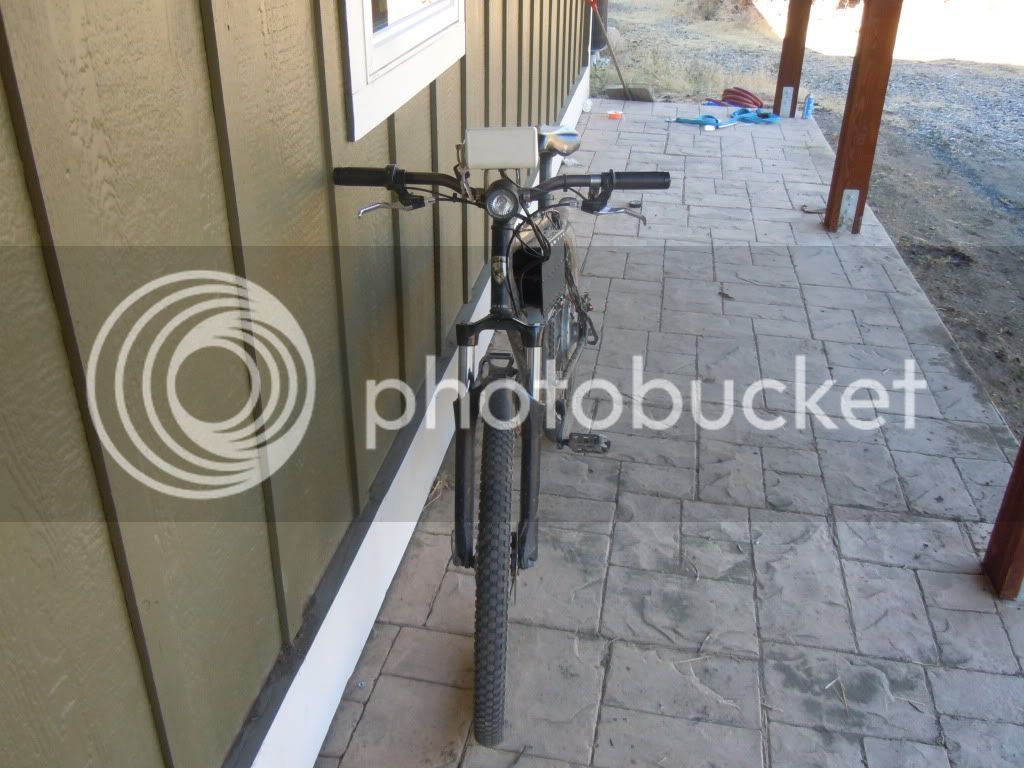
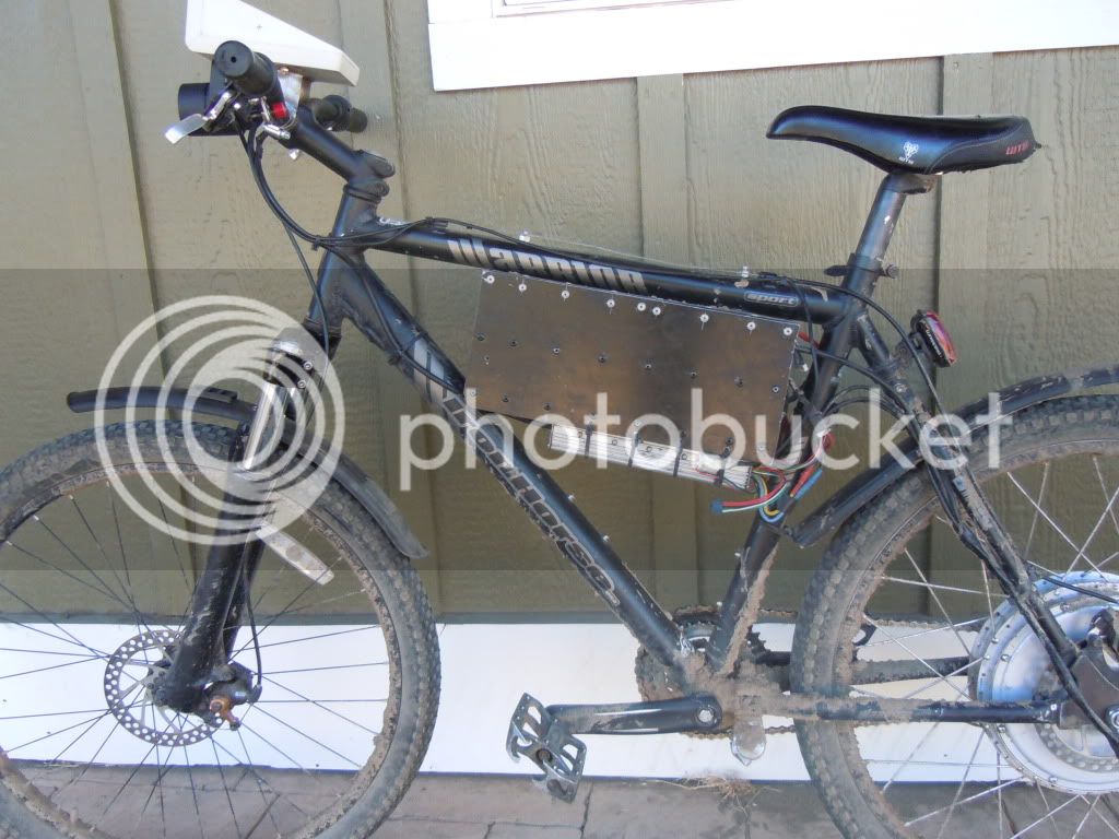
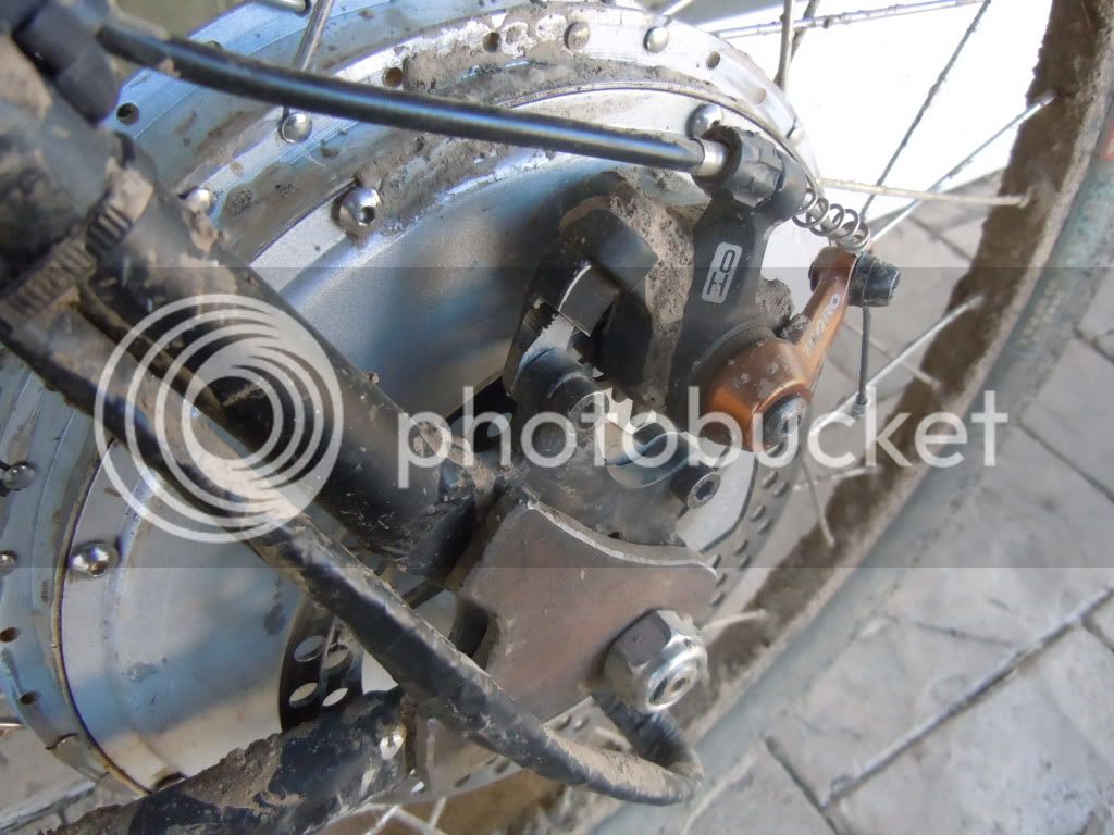
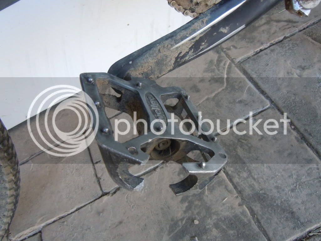
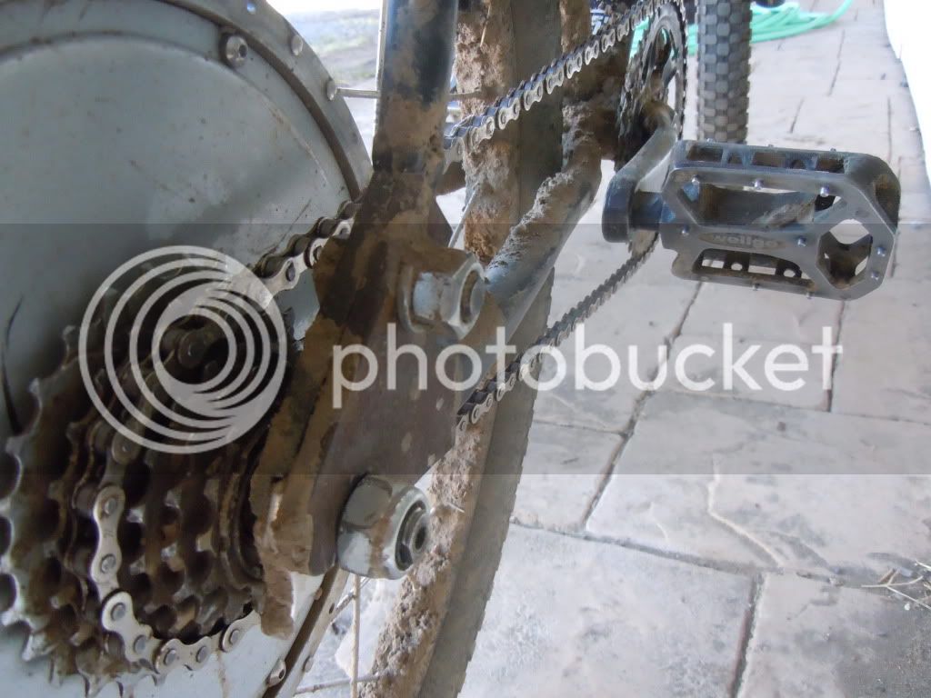
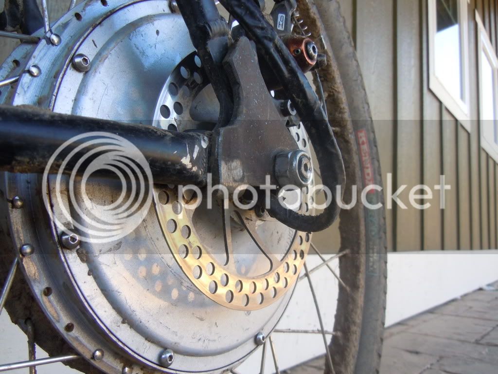
sigh, cameras are not meant to be. soo, i took it apart, re-soldered all the itty-bitty wires and it works! so, about the bike, Yes it is muddy it just went up and down a bunch of trails in Montana while it was raining, Including some accidental mud bogging, er getting stuck :D got mud all the way to the disks :twisted:. I was worried about the controller at first, but lyen seals em up pretty good. A+ work man!

DSCN0995.jpg


DSCN0994.jpg


DSCN0993.jpg


DSCN0990.jpg


DSCN0992.jpg
 
The box on top- soon to be an instrument panel, is from a place called OKW enclosures, I got it as a free sample :D . and they are definitely worth buying from, the box is sealed and slots together then held in place with screws. its DAMN tough! it bent the steel mounts it was attached to when I flipped my bike, the mounts never recovered :cry: . Heres some more pics.

DSCN1000.jpg


My uber ghetto single speed :evil:


DSCN0998.jpg


DSCN0997.jpg
 
LIke the T.A. design! slick!
 
Torque Arm........Get your mind outta the gutter......While you are there, get mine too!! :mrgreen:
 
so, got the regen button hooked up today, and it ran great, lots of stopping power. the only problem i am seeing, is that it is dumping ALOT of energy into the batteries at once as it brakes about 40-50% of what the disks can do. the voltage limit on the ebraking seems to be what is determining it, as when i put it on 60v, you cant tell if the button is being pushed or not, but on 70v it almost locks up the back tire it brakes so much. is there any other way to adjust this? i have a lyen 18fet controller.
 
Farfle said:
so, got the regen button hooked up today, and it ran great, lots of stopping power. the only problem i am seeing, is that it is dumping ALOT of energy into the batteries at once as it brakes about 40-50% of what the disks can do. the voltage limit on the ebraking seems to be what is determining it, as when i put it on 60v, you cant tell if the button is being pushed or not, but on 70v it almost locks up the back tire it brakes so much. is there any other way to adjust this? i have a lyen 18fet controller.
Well, you could change the resistor that alters the regen voltage (like you have already to 70v from 60v) to one of those digipots, then control the digipot from an analog sensor on your ebrake handle. Set up the digipot range (with external series or parallel resistors) so that squeezing the brake lever just a little bit starts at a regen voltage just a few volts above your pack voltage, and the harder you squeeze the higher the voltage goes, which increases the current dumped into your pack and increases the braking force. This is an experiment I'd like to try eventually, as it should work on any controller that allows this. (in theory you could just change the resistor to a pot and wire that up to your ebrake handle, but it may react badly to having such long wires in the circuit--the digipot eliminates that by putting the pot at the physical location the resistor(s) were, but controls the digipot from your brake levers).

Other than that, no other way that I've found so far, although I have a theory that PWMing the ebrake line *might* modulate the braking. The PWM signal would come froma throttle sensor used in place of the ebrake sensor/switch, and a magnet on the brake lever, so that it would give an analog braking signal.

If the controller has the "throttle braking" option, then you could enable that and then I think that engaging the brake and modulating the throttle does the same thing as what I want to do with just the ebrake lever.

The catch with PWMing the ebrake input is that at least with the Lyen (and probably the other Infineon) 6FET controllers, AFACT there is a delay from the time ebrake is let go and the time the controller kicks back on, of at least half a second. I don't see a way to disable that in the software. It's possible there is an RC filter on the ebrake line coming in, and I'll have to figure out the schematic for that portion to see if it does. If so, I could simply remove the capacitor or change it to a very tiny one, or decrease the resistance, or both, so that it doesn't do this. If there's no RC filter then it's being done inside the MCU, and the only way to change that is to have someone in China rewrite the program so that it does not do this (unless someone here can do this, which I doubt, without source code/etc., or rewriting the entire controller program from scratch).

Older analog regen-capable controllers probably can be PWMed for the ebrake input to do this, easily. I have one I need to repair and try that out, one of these days.
 
Regen brake made me eat it today. I was going 35ish mph (almost top speed) and hit the button on accident and it locked up the back tire i managed to just lay it down, so no crazy flipping or anything :D .Was wearing a poofy coat, and full-face helmet, so not even any road rash :D . just a couple briuses, a torn coat :( and another re-bend to the mounts for the instrument panel.
 
ok, doing a big jump in the next week (actually a couple of jumps) first off, controller modding! need to solder in a new resistor... second, high voltage! 24s of 4.2 volt lipo! and third, converting meanwells to chargers! anybody have any suggestions on how to series up a couple of 48v meanwells, and tweak them up to 100 volts? i have a balancing charger that i have made a balancing harness for but all batts have to be in paralell, which involves alot of hooking and unhooking. esp for 24s
 
There is a whole thread dedicated to converting various MW to chargers and such; a more recent version of it appears to be a breakdown/summary of it. I don't have a link handy to either, though. I think theyre both in the batteyr tech forum.
 
ok, not sure whether someone knowledgeable about this will stumble onto this topic or not, but there seems to be a pretty good deal on 48v 3a psus. which are fine for my cause as i only have about 6 ahrs of battery to charge, but from what i read, i was wondering what resistor mods/current limiting mods i would have to do. Even at the psu's stock voltage, i would get 4v per cell, and if the fine adj pot will go up high enough (.75v per psu), I can get a full charge (100.8v).

Heres a link to the PSU

http://cgi.ebay.com/48V-DC-3A-145W-Regulated-Switching-Power-Supply-New-/290457275192?pt=LH_DefaultDomain_0&hash=item43a09a4b38
 
It also depends on which version of teh MW that is; if it's the one with the hiccup mode current limit, it's not as easy to use IIRC.

There is a thread called something like "switch mode supply mod" being posted to a lot recently that has another way to mod the MW, different from the original way.
 
i looked thru it, actually, i read page 1-15 then skipped to the end and read backwards from there :oops: , and got a lot of confusion on what exactly you do to mod one, i don't need to do a voltage mod,just a current limit to keep it from burning up. I have a friend that has a circuit built that if one of two thermistors gets over a certain temp (one for psu, one for batt pack), or voltage gets to charged-pack voltage, it shuts off a 100vdc relay in between the batt and psu, and a 110 v relay attached to the ac-in. this "safety circuit" is because i will be charging it at school, and i don't want to ruin my/robotics teams/ebike's reputation if i light something on fire :eek: .
 
These circuits require very little parts to build, I may post the schematic for others to use, probably will find some constructive criticism while im at it :roll:
 
Farfle said:
i don't need to do a voltage mod,just a current limit to keep it from burning up.
Then if I understand what they are doing in the most recent stuff in that thread, on pages 33/34 (maybe earlier too) then there is a simple small PCB you could make that does what you want; actually I think there are two concurrent designs being worked out, but I think at least one and probbaly both have working versions already. IIRC one goes inside the MW and the other connects to the pins/terminals outside.
 
Well, jason has already set up and breadboard-verified the board, tomorrow he will probably set up the PCB and start soldering, he needed the project, so very little cost to me, and it works : ).
 
oook, biulding a fechter current limiting board, and wondering if these PSU's will work, I only have 6ahrs of lipo, so a 3a charge rate should be fine, a 2 hr charge suits my needs perfectly.

heres a link to the PSU's

http://cgi.ebay.com/48V-DC-3A-145W-Regulated-Switching-Power-Supply-New-/290457275192?pt=LH_DefaultDomain_0&hash=item43a09a4b38
 
Yay, last couple weeks have been really busy. Had to replace a cell that went bad, got a cycle analyst, picked up a set of 48v meanwells and a fetcher board :D .
 
nooo! the charger I have has been murdering my cells!!! :evil: all the #3 cells in my 3 8s packs are toast! :evil: Good news is, just got back from duck hunting and the shotgun was still in the truck.
:twisted: :twisted: :twisted: . 3-1/2" steel shot does a number on an icharger :twisted: :twisted: :twisted: .
 
Remind me not to be a piece of defective electronics around you. ;)

I wonder what exactly failed in it that caused only the #3 cells to die? Guess we'll never find out. :p
 
well, i looked at it, and there's is a series of small black SMD's that were fried along one trace. that charger was garbage though, from day one I would have to "trick" it into thinking it was charging the right battery as whenever i discharged them below 3.5 v/cell it would recognize it as a 7-cell, then complain that it was the wrong cell count halfway thru charging it, a week after that the fan gave it up, so i replaced it. Recently the screen has been dieing and the left half completely stopped functioning. Yesterday, I tried using it to charge my pack before I went duck hunting and it kept giving me an over temp error, after being in the freezing garage for several days :roll: . so I un-soldered the thermistor and soldered in a resistor matching its "cold" value and it helped for a little bit. Then it completely stopped listening to the thermistor, and read 88c no matter what I did to it. thats when i gave up and shot it. biggest flaming piece of crap I have ever bought.
 
Somehow that phrase just leaps right out at you, you know? "That's when I gave up and shot it". :lol:

I don't blame you, though. ;)
 
Back
Top