
badboy1999
1 mW
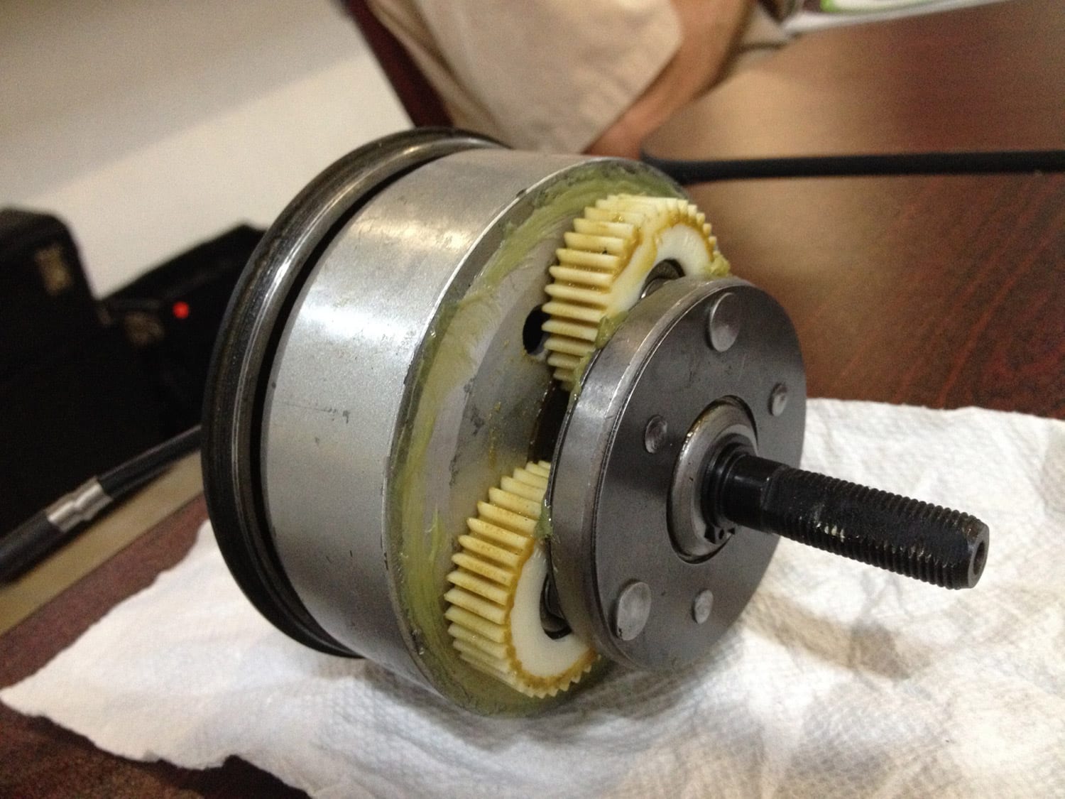
I've got a secondhand wheel with Tranz-X motor (250w 24v it says) but I'm trying to figure out the hall sensor pinout. The motor looks exactly like this BTW from the inside:
Which maybe isn't really relevant since I'm just trying to figure out the Hall pinout which my Kelly controller needs. I took a lab power supply set to five volts, attached a 1000 Ohm resistor to the + of the power supply to limit current to max 5mA, and connected this 5v with a resistor and the 0v to the hall sensor connector in every possible way (6 possiblities for where I put the 0v, 5 for the 5v -> 30 combinations. I measured the voltage over these two hall sensor pins and wrote them down.
My theory is, the voltages are a measure for how much current these two pins are drawing, and I was expecting to find two wires that had a current consumption that was different from the rest and no current consumption (measured as 5v) when wired in reverse. This is based on my understanding the expected behaviour of the power wires going to the hall sensors.
I also expected to find the three signal-wires (it's a standard three phase ebike motor), because I expected them to be closed connections to one of the power pins (lots of current drawn, so maybe 0v it it's a fet inside the hall sensor or ~0.7v if its a bipolar transistor) and open connections to the other power pins. I hope everyone is still following here, my understanding of electronics is not the greatest so please correct me if I'm wrong.
These are the measurements I've got and I'm confused:
Pin 2 and 5 seem special. But they're also drawing current in reverse when only connecting these two pins. In addition, these pins don't have 'special' voltages when hooked up, their voltages (meaning their current draw as well, Ohms law) are very much the same as the suspected sensor pins.
Another confusing thing: they're drawing a lot of current. Either a total of ~2.4mA or 4.3mA.
Third confusing thing: I was thinking one of the six wires was a temperature sensor. But there's just 2 strange wires, and then 4 suspected sensor wires.
I tried using a LED to find out if the suspected sensor wires indeed are sensor wires (rotating the wheel backwards so it doesn't freewheel, 500 Ohm resistor between LED and gnd/plus, tested this on multiple pins, but no combination gets the led blinking when spinning the wheel).
What can I do? All thoughts appreciated!
")