samuraijack255
1 µW
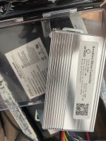
I got an escooter from a friend that I’m trying to bring back to life. He said someone told him the controller was damaged. I ordered a similar one from Amazon. Now the display powers on but the throttle doesn’t activate the motor.
I ran tests on various parts with a multimeter and still can't find the issue. Reaching out to y’all to see what else I can do or if one of my tests was incorrect.
Battery Voltage
Voltage is 41.2V (rated 36V) so it seems fine. However, the battery alert icon is blinking on the display, even after charging for 4hours. Not sure if that’s a glitch or a sign that something is wrong.
Motor
I did a resistance test. Wheel rotated reasonably well when all phase wires were disconnected. When I shorted 2 phases at a time, the wheel resisted rotation, as expected.
Hall Sensors
The sensor voltages are varying from 0-4.96V as I rotate the wheel. So I assume the hall sensors are working fine. Further, the voltage on the controller side hall wires is a constant 4.9V (when controller is powered and hall cable is not connected to the motor). So the controller side hall wiring seems fine.
Controller MOSFETs
The reverse resistance is high (19.7K Ohms, each phase wire to negative battery connector). The forward resistance is high (1 ie OL, between each phase and positive batt connector). Thus, the MOSFETs seem fine.
Throttle and Brake Signal
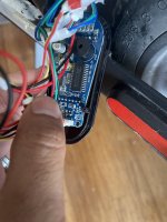
The throttle and Brake signal wires are sending the right voltages via the signal wires. However, the throttle doesn’t directly connect to the controller - it connects to the display circuit that seems to have its own ICs. The display in turn connects to the controller. It looks like the display and controller communicate via a TX-RX pair line.
I checked the voltage on the TX line and gnd and noticed that normally it is 4.56V. When I press the brake, it goes up to 4.59. When I do a full throttle, it reaches 4.59V. Does this mean the display circuitry is working fine and that the issue has to be further downstream?
Phase Wires
I’m wondering if the problem is in the last step - controller not sending the appropriate signal/voltage to the windings. Is there a way to test this? I checked the voltage between each phase wire and battery gnd. It is a constant 0.63V. Varying the throttle does not seem to change this. Shouldn’t the voltage increase in proportion to the throttle? Or should I be measuring the current?
Is there any other test I can do?
Maybe the answer is already here and I've overlooked a detail.
I ran tests on various parts with a multimeter and still can't find the issue. Reaching out to y’all to see what else I can do or if one of my tests was incorrect.
Battery Voltage
Voltage is 41.2V (rated 36V) so it seems fine. However, the battery alert icon is blinking on the display, even after charging for 4hours. Not sure if that’s a glitch or a sign that something is wrong.
Motor
I did a resistance test. Wheel rotated reasonably well when all phase wires were disconnected. When I shorted 2 phases at a time, the wheel resisted rotation, as expected.
Hall Sensors
The sensor voltages are varying from 0-4.96V as I rotate the wheel. So I assume the hall sensors are working fine. Further, the voltage on the controller side hall wires is a constant 4.9V (when controller is powered and hall cable is not connected to the motor). So the controller side hall wiring seems fine.
Controller MOSFETs
The reverse resistance is high (19.7K Ohms, each phase wire to negative battery connector). The forward resistance is high (1 ie OL, between each phase and positive batt connector). Thus, the MOSFETs seem fine.
Throttle and Brake Signal
The throttle and Brake signal wires are sending the right voltages via the signal wires. However, the throttle doesn’t directly connect to the controller - it connects to the display circuit that seems to have its own ICs. The display in turn connects to the controller. It looks like the display and controller communicate via a TX-RX pair line.
I checked the voltage on the TX line and gnd and noticed that normally it is 4.56V. When I press the brake, it goes up to 4.59. When I do a full throttle, it reaches 4.59V. Does this mean the display circuitry is working fine and that the issue has to be further downstream?
Phase Wires
I’m wondering if the problem is in the last step - controller not sending the appropriate signal/voltage to the windings. Is there a way to test this? I checked the voltage between each phase wire and battery gnd. It is a constant 0.63V. Varying the throttle does not seem to change this. Shouldn’t the voltage increase in proportion to the throttle? Or should I be measuring the current?
Is there any other test I can do?
Maybe the answer is already here and I've overlooked a detail.