First Hub Wheel Build

If ground is shared via the battery between the controllers, then that should be the only ground they share to prevent ground loops.

Power is only needed from one controller; doesn't matter which one as long as it's always on when the throttle needs to be used.

Signal splits to both.

Teklektik's 2WD thread (a Yuba Mundo, IIRC) covers a lot of things about wiring up a multicontroller system, if it's helpful.


If you ever think you'll need to "tune" the controllers' response to the throttle, to make them equal or unequal, you can put the signal to the center tap of a pot (say, 10kohm) and each outside pin of the throttle to one of the controllers. This can give you a small amount of tuning control to make the throttle signal different between the two. How much control depends on the internal resistances of the controllers and the current that flows thru the resistors (current is typically very low). If you need more tuning than that it may require active circuitry, or programmable throttle response in the controllers.
 
In response to me reusing old spokes that old rim was beat up and in the process I had broken 8 to 10 spokes and as I try to replace them quickly I had to contort them in some terrible ways to get him to fit in the motor and rim so it was unfair for me to really use those spokes over again. I will try and get the bump out later.
Let us know how your will bill came out doesn't have a bump in it how about side to side. How true were you able to get it?
 
Ah, that’s two throttles one controller, I’m looking at the reverse.
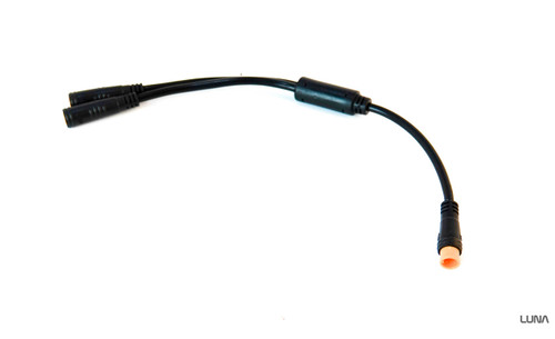
I think you need a male (to mate with the Bafang throttle female) and two females, right?

(EDIT sorry, I was looking at a Bafang throttle and it had a female connector, but see they ones with male connectors as well).

Same as this one on Luna's website:
 
Last edited:
You don't just want a splitter, you want one that does not connect the 5v from one of the controllers to the throttle, and preferably not the ground either. (so the throttle only gets one 5v, and preferably only one ground).

So if you get a true splitter, you'll need to do surgery on it or on one of the controllers that connects to it, to disconnect those wires and leave only the signal. The "best" way to do it if you need the waterproofing of those connectors and wiring is inside the controller, by cutting or desoldering the 5v (and ground).

(if you connect the 5v from both controllers together thru the throttle splitter, it might not cause any problems at all, but it's possible for them to be slightly different in voltage, so the lower voltage controller will draw current from the higher voltage controller, and this may exceed the regulator's ability to supply, and overheat. If it just causes it's voltage to drop, then that's ok because it will then drop to match the other controller and they'd then both supply current--but the drop in voltage will cause more heating, and if it's too much, it may fail eventually. (the flip side is that if it fails open-circuit then the 5v from the other controller may operate things for a while, but eventually it would also overheat and fail).)
 
You don't just want a splitter, you want one that does not connect the 5v from one of the controllers to the throttle, and preferably not the ground either. (so the throttle only gets one 5v, and preferably only one ground).

So if you get a true splitter, you'll need to do surgery on it or on one of the controllers that connects to it, to disconnect those wires and leave only the signal. The "best" way to do it if you need the waterproofing of those connectors and wiring is inside the controller, by cutting or desoldering the 5v (and ground).
Not sure about not having the ground. The signal wire needs a reference point. As far as modifying the harness or controller, I'd probably just snip the 5V pin from one of the connectors.
 
That's also a solution (which I didn't think of).

(but it isn't reversible if for any reason (can't think of one ATM) you need that pin later on).

Battery negative is ground, and if they're running on the same battery goes to both controllers (if they dont' both run off the same battery, then tying the battery grounds together is a fix for that, assuming any current monitoring / shunts in the wiring allow this easily).

If there are multiple grounds in a system, especially if there are different currents in them, you can have a ground loop, which can cause problems with voltage referencing among other things.

The battery ground is the "most solid" lowest-resistance ground in the system, if they share this, and so should be least affected by current flow, though it has the highest current flow already thru it during operation.

Whether any of this affects actual operation will depend on the system and what is happening at any particular moment.

A wiki page about ground loops that explains fairly well
 
Battery negative is ground, and if they're running on the same battery goes to both controllers (if they dont' both run off the same battery, then tying the battery grounds together is a fix for that, assuming any current monitoring / shunts in the wiring allow this easily).
Ah, I forgot about the battery. (y)
 
I share a throttle on my 2WD setup.
The front hub controller is the "Master" running the 5v, GND and signal to the throttle, I then made a JST harness to share the Signal wire to the rear controller.
Same for PAS signal also, Front controller has the standard wiring and the rear just gets a shared Signal wire to it.
I do not share any of the 5v or GND across the controllers, Im assuming/hoping the shared Battery Connection keeps all the grounding gremlins in check.

Im not sure how I would address this issue if I was running seperate batteries...
 
I did buy a Minoura Workman Pro Wheel Building and Truing Set, but have also built wheels in a spare pair of front forks and an old frame using cable ties as straightening guides, my trick if a trick, is to wind the nipples onto each spoke and stop just before the spoke thread disappears into the nipple, then go round the spokes tightening the nipples say 3 turns each followed by another 2 or 3 turns dropping down to 1 as the tension builds on the spokes, this give you a fairly straight wheel to start with before putting the wheel into the straightening jig, bar final straightening I can put the wheel together in about 20 minutes. I have always used the Sapim spoke calculator along with the Sapim Strong spokes, so far none of the wheels have fallen apart. Being a retired engineer I do have the feel for checking the spoke tension.
 
Back
Top