sdobbie
100 W
Hi everyone, I am designing my own vesc based controller and have a few questions. I am designing it based on this
https://vesc-project.com/sites/default/files/Benjamin Posts/vesc_75_300.pdf
How do I I flash the firmware to the MCU using the st link? I am using the STM32F405RGT6. There will be different firmwares depending on whether the design uses the DRV chip or not I'd imagine.
My first design will follow the linked pdf exactly apart from the following differences
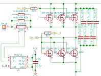
It will be 6 fet so instead of the three current sense resistors in parallel should I just use 1 resistor of 0.0005 ohms? Or are three resistors used for a good reason and must be the same value as in the diagram?

Linear regulators in to220 package heatsinked to the casing will be used to supply the 3.3v and 5v for the MCU and other electronics on the pcb rather than the failure prone switching regulators I have dealt with in the past which resulted in a vesc I bought failing. The 12v to these regulators will be supplied externally from a small 2.1 ah 12v accessory battery kept charged from the main hv battery through a dc converter as is the standard in electric cars. I am doing this also to keep the controller itself robust and simple to build.
https://vesc-project.com/sites/default/files/Benjamin Posts/vesc_75_300.pdf
How do I I flash the firmware to the MCU using the st link? I am using the STM32F405RGT6. There will be different firmwares depending on whether the design uses the DRV chip or not I'd imagine.
My first design will follow the linked pdf exactly apart from the following differences
It will be 6 fet so instead of the three current sense resistors in parallel should I just use 1 resistor of 0.0005 ohms? Or are three resistors used for a good reason and must be the same value as in the diagram?

Linear regulators in to220 package heatsinked to the casing will be used to supply the 3.3v and 5v for the MCU and other electronics on the pcb rather than the failure prone switching regulators I have dealt with in the past which resulted in a vesc I bought failing. The 12v to these regulators will be supplied externally from a small 2.1 ah 12v accessory battery kept charged from the main hv battery through a dc converter as is the standard in electric cars. I am doing this also to keep the controller itself robust and simple to build.

