A Small 6 fet Vesc 6 Design

Why would you not use the smt service? That's mad. It takes a tiny fraction of the time to add the jlcpcb part number as it does to search mouser, add to basket, open the bag and solder it... And you do away with the hassle of dry joints and... 5 hours of soldering... etc. For 5+ PCBs...

The price per part of also cheaper from jlc mounted than you can get from mouser on a tape.

You'd have to be a masochist to solder something yourself that jlc has.
 
sdobbie said:
I have managed to get all the parts needed apart from the canbus chip which isn't essential at the moment and the X50328MSB2GI clock crystal. Are there any substitutes I can use for the crystal or even omit it? As far as I know, the crystal is only needed for USB to work.

I have a VESC without a crystal that repeatably loses CAN bus communication at higher temperatures with a measurable bit rate difference, strongly suggesting clock drift due to temperature.
 
drdrs said:
sdobbie said:
I have managed to get all the parts needed apart from the canbus chip which isn't essential at the moment and the X50328MSB2GI clock crystal. Are there any substitutes I can use for the crystal or even omit it? As far as I know, the crystal is only needed for USB to work.

I have a VESC without a crystal that repeatably loses CAN bus communication at higher temperatures with a measurable bit rate difference, strongly suggesting clock drift due to temperature.

I've observed pwm frequency errors of 2.5% on stm32 using internal clock at ambient temperature.
 
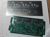
The issue is that they didn't have a lot of the parts required so I would end up having to solder a lot myself anyway. That's why I ordered the stencil so I can apply the solder, place all the parts and then use a reflow oven. Before I buy a reflow oven though, i will just heat the pcb up on top of a hot plate at maybe 120C and use a hot air gun to solder for the prototype stage.

The closest I can find is this but it's 100 ohms instead of 60 to 80

https://www.lcsc.com/product-detail/Crystals_JYJE-5TG280000ZYLBC_C2686259.html
 
drdrs said:
I have a VESC without a crystal that repeatably loses CAN bus communication at higher temperatures with a measurable bit rate difference, strongly suggesting clock drift due to temperature.

Accurate CAN bit timing requires an accurate clock source once you get into the 500k-1M baud rate range. Reduce your baud rate to 250k if possible and that will help alleviate the issue. Don't underestimate the importance of the crystal, especially for CAN and USB.

The tolerance of internal RC oscillators is pretty poor compared to a crystal. Some of the newer devices from TI use different resonators that will basically do away with crystals.
 
sdobbie said:
Before I buy a reflow oven though, i will just heat the pcb up on top of a hot plate at maybe 120C and use a hot air gun to solder for the prototype stage.

Very admirable of you jumping straight into the deep end on a project like this! I would have recommended you take it a bit slower and read through all the threads of other builds to learn from what everyone else has done before going all in on a design, but that is a great way to learn.

BTW there's nothing wrong with the V4 hardware, it works just as well as the V6 when used within the constraints of the hardware.
 
sdobbie said:
The issue is that they didn't have a lot of the parts required so I would end up having to solder a lot myself anyway. That's why I ordered the stencil so I can apply the solder, place all the parts and then use a reflow oven. Before I buy a reflow oven though, i will just heat the pcb up on top of a hot plate at maybe 120C and use a hot air gun to solder for the prototype stage.

The closest I can find is this but it's 100 ohms instead of 60 to 80

https://www.lcsc.com/product-detail/Crystals_JYJE-5TG280000ZYLBC_C2686259.html

I can't see that not working.

There are all manner of appnotes on the correct drive resitance, correct capacitance... and in the end, the ST reference designs on Nucleos, and most boards I have ever seen don't bother with drive resistors and just slam 10-20pF caps on... Somehow the drive resistor kerfuffle doesn't seem to be a real thing. I suspect ST have some cunningness on the chip that avoids overdriving.

Just try it and if the frequency isn't right, look further into the capacitor values.
 
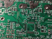
The boards arrived today and they look good. I am just waiting on the clock crystals and a few other things. Very happy with the board quality so far.
1.jpg
 

Attachments

  • 2.jpg
    2.jpg
    570.9 KB · Views: 933
I always love getting boards in.

I don't know if you're experienced with bringing up boards, especially power ones, but you might consider a few pointers... Apologies if I'm teaching you to suck eggs.

1) you might consider just popping on an MCU to see if it programs and clocks. No point populating everything if that doesn't work.

2) if you weren't supplying externally I'd say build up your DCDC bits first and check they're stable before you let them burn your MCU.

3) consider programming from st cubeMX, you can test out peripherals, pwm, ADC current reading etc without having VESC set fire to your board.

4) get a current limiting PSU, don't go strapping it to a lipo battery until you know it works. 200mA is plenty for the MCU 3v3 rail. You'll need about 5A 24V to have VESC successfully run a detection. No idea why it forces so much current through motors for detection. TBH i usually wonder why VESC does things. I have one home made VESC board of of 5 that for no apparent reason won't work... Detection fails, disconnects the USB, waits 10 seconds before injecting a truly terrifyingly loud sound into the motor and tripping out a 10A 48V PSU.

Above all, good luck. I'm not as excited as you I'm sure, but I love to see other people's projects in action and this is the most exciting stage!
 
sdobbie said:
All very good ideas I never thought of. My concern though is heating the MCU multiple times. Might be bad for it.

It is bad for it. They take a reasonable amount of heat but they do die. I've killed a few.

I rarely solder up full boards now. Haven't done one for nearly a year. If I have to solder things around an expensive chip I put tin foil over the chip to protect it.

Don't learn to do SMT with 10$ stm32s... I presume you've done this before right? I usually pick and place under a microscope.

Every heat cycle oxidises the surface and you need more flux and it gets harder each time you reheat.
 
I have done a lot of surface mount in the past down to 0603 size. The MCU will be my biggest challenge yet to solder but I'm sure it's doable with what I have.

As for the software side, what compiler should I use in Windows to give me the binary for the mcu after I have edited the hwconf files?
 
Compiling from windows is a pain. It'll be less effort to just get a raspberry pi or mint box, then it's literally like 10 commands into the terminal.

Lqfp 64 is easy enough even with just a soldering iron once you're used to it. With stencils and paste it's absolutely fine... Once you've had a few practices.
 
Will just go the linux route in that case. Do you have a link to any instructions on how to compile it on ubuntu? I can just install ubuntu on my main pc on a separate ssd.
 
Shout out for Linux mint. Better in every way. Did VESC easily on it.
 
There is also an explanation on Github, under the files:
https://github.com/vedderb/bldc

This method didn't work on the newest Ubuntu/mint (but you can alway try):
Code:
sudo add-apt-repository ppa:team-gcc-arm-embedded/ppa
sudo apt update
sudo apt install gcc-arm-embedded

But method one, downloading directly from arm.com and copy to usr/local did work for me exactly as described on Github. I made an custom application, a 'Cruise Control' directly integrated in the thumb throttle, so I had to build it myself.

And the commands for Ubuntu or Linux are exaclty the same so I wouldn't know why one is better than the other....;). But I'm personally a huge fan of Mint.

You can install it on a separate SSD, or on the same disk, in the installer you can choose how much space you want to reserved for Linux, I made once a video about it:
https://youtu.be/GzcdoF62Tn4

At boot you can choose if you want to start Windows or Linux.
 
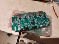
Thanks for the help everyone. I have good news. I haven't compiled my own firmware yet, but I have flashed a pre compiled vesc 6 bin file to it resulting in the red LED flashing when I connect 12v power to the 3.3v regulator. I soldered the whole thing at once and did a short circuit test across all power inputs on the board then just powered it. The flashing LED would suggest that the MCU is running normally. I left it sitting like this for a few minutes and the regulator only gets slightly warm with no heatsink on it.

IMG20211020221156a.jpg
 
Looking neat. I'm also searching a relative low power VESC without the DRV, that's why I'm following this topic.

I already had the intention to make a video about compiling the VESC firmware also as a reference for later:
https://youtu.be/lclRbZko9Us
 
Further testing successful with no magic smoke. Managed to connect to the vesc tool using a usb to serial cable. Don't care much for direct usb connection to be honest.

I am going to install linux mint cinnammon version and try to set up the compiler, unless I can use the mint xfce version which is the lightest and smallest.

The only issue I am having in the hwconf file is how to edit so that it works with only one temperature sensor which I have attached to the pin #define ADC_IND_TEMP_MOS 8

which is actually pin 17 on the MCU .

Would I just change it from
Code:
#define ADC_IND_TEMP_MOS		8
#define ADC_IND_TEMP_MOS_2		15
#define ADC_IND_TEMP_MOS_3		16

to
Code:
#define ADC_IND_TEMP_MOS		8
#define ADC_IND_TEMP_MOS_2		8
#define ADC_IND_TEMP_MOS_3		8

Would that maybe result in too many unneccesary ADC reads?
 
Just need to look in the .c file, where it has the temeprature sensor as used defined. the others can sit there and happily read open pins AFAIK... Worked for me.

There's a macro.

Code:
float hw75_300_get_temp(void) {
	float t1 = (1.0 / ((logf(NTC_RES(ADC_Value[ADC_IND_TEMP_MOS]) / 10000.0) / 3380.0) + (1.0 / 298.15)) - 273.15);
	float t2 = (1.0 / ((logf(NTC_RES(ADC_Value[ADC_IND_TEMP_MOS_2]) / 10000.0) / 3380.0) + (1.0 / 298.15)) - 273.15);
	float t3 = (1.0 / ((logf(NTC_RES(ADC_Value[ADC_IND_TEMP_MOS_3]) / 10000.0) / 3380.0) + (1.0 / 298.15)) - 273.15);
	float res = 0.0;

	if (t1 > t2 && t1 > t3) {
		res = t1;
	} else if (t2 > t1 && t2 > t3) {
		res = t2;
	} else {
		res = t3;
	}

	return res;
}

Just remove everything except return whichever one your sensor is.
 
I tried to compile after installing everything but I am getting this error

s@s-All-Series:~/vesc_firmware$ make

arm-none-eabi-gcc -x assembler-with-cpp -c -mcpu=cortex-m4 -Wa,-amhls=build/lst/crt0_v7m.lst -DCORTEX_USE_FPU=TRUE -DTHUMB_PRESENT -mno-thumb-interwork -DTHUMB_NO_INTERWORKING -mthumb -MD -MP -MF .dep/crt0_v7m.o.d -I. -IChibiOS_3.0.5/os/common/ports/ARMCMx/devices/STM32F4xx -IChibiOS_3.0.5/os/ext/CMSIS/include -IChibiOS_3.0.5/os/ext/CMSIS/ST -IChibiOS_3.0.5/os/rt/include -IChibiOS_3.0.5/os/rt/ports/ARMCMx -IChibiOS_3.0.5/os/rt/ports/ARMCMx/compilers/GCC -IChibiOS_3.0.5/os/hal/osal/rt -IChibiOS_3.0.5/os/hal/include -IChibiOS_3.0.5/os/hal/ports/common/ARMCMx -IChibiOS_3.0.5/os/hal/ports/STM32/STM32F4xx -IChibiOS_3.0.5/os/hal/ports/STM32/LLD -IChibiOS_3.0.5/os/hal/ports/STM32/LLD/DACv1 -IChibiOS_3.0.5/os/hal/ports/STM32/LLD/GPIOv2 -IChibiOS_3.0.5/os/hal/ports/STM32/LLD/I2Cv1 -IChibiOS_3.0.5/os/hal/ports/STM32/LLD/OTGv1 -IChibiOS_3.0.5/os/hal/ports/STM32/LLD/RTCv2 -IChibiOS_3.0.5/os/hal/ports/STM32/LLD/SPIv1 -IChibiOS_3.0.5/os/hal/ports/STM32/LLD/TIMv1 -IChibiOS_3.0.5/os/hal/ports/STM32/LLD/USARTv1 -IChibiOS_3.0.5/os/hal/ports/STM32/LLD/FSMCv1 -IChibiOS_3.0.5/os/various -IChibiOS_3.0.5/os/hal/lib/streams -Imcconf -Iappconf -Ihwconf -Iapplications -Inrf -Ilibcanard -Ilibcanard/dsdl -Iimu -Iimu/BMI160_driver -Icompression -Iblackmagic -Iblackmagic/target -IChibiOS_3.0.5/ext/stdperiph_stm32f4/inc ChibiOS_3.0.5/os/common/ports/ARMCMx/compilers/GCC/crt0_v7m.s -o build/obj/crt0_v7m.o
make: arm-none-eabi-gcc: Command not found
make: *** [ChibiOS_3.0.5/os/common/ports/ARMCMx/compilers/GCC/rules.mk:218: build/obj/crt0_v7m.o] Error 127
 
It looks like you don't have the embedded arm gcc compiler installed or it is not in the path.
 
Back
Top