Cheap FOCer (VESC 4.12 based design)

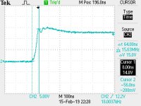
So I increased the gate resistor from 4.7ohms to 10ohms. It only helped slightly. Doe anyone know what value to stop at if I were to keep increasing?

Also, what would be the slowest rise time(slew rate) acceptable for all of this?
 
You'd want your combined rise and fall times to be less than 1% of the switching period, or 500ns.

I wouldn't increase the gate resistor more than 20~ ohms otherwise it will take a long time to enhance the MOSFET for good rdson, if you do use 20ohms I suggest you parallel if with a diode for fast turn off though.

Yeah, I can see how it would be basically a re-layout, but I think it is worth looking into, so definitely check out what it is like with the capacitor.
 
Thanks for all the help so far! FYI the default FOC switching frequency for the VESC is 30kHz so 333ns for the 1% rise/fall time. Slower switching works but is noisier.

I've tried a combination of things so far including adding another bulk cap at the end. The bulk cap(1000uF) didn't seem to have an effect. I did eventually switch to measuring with an active scope probe using short leads and measured 18V spikes at worst with 12V supply. I also measured the supply itself and was seeing the 18V spikes there as well. It looks like I need to switch to using a battery for my supply and use short power cables. The one's I'm using now are super long and probably throwing me off. Maybe optimizing my power supply will help and the ringing will be reduced.

I'll retest all of the suggestions once I've fixed my test setup.
 
Bulk capacitors won't help with the ringing. They are way to slow for that. The bulk capacitors serve two purposes. 1) to keep Vbus stable and reduce voltage drop. Aim for Max 1-5% voltage drop. (Easy to accomplish with electrolytic capacitors) 2) to supply ripple current to the motor.
 
You could try some low value, low esl capacitors between Vbus and gnd. As close as possible to the half bridges. But really lowering the loop inductance would be the best fix.
 
I've tried ceramic and film caps of values from 0.01uF to 1uF for each set of FETs on the bridge. They certainly reduce the duration of the ringing but don't bring down the initial voltage spike enough. I know lowering loop inductance addresses the root cause of the problem and I've taken actions to improve this in the PCB design already. Now I'm just trying to get this particular prototype with all of it's flaws to just operate well enough for loaded testing.
 
As a last resort you could use an RC snubber circuit on the three phases to dampen the ringing. But this will add losses.
see page 12 of the following document:
https://e2echina.ti.com/cfs-file/__key/communityserver-discussions-components-files/24/8244.Ringing-Reduction-Techniques-for-NexFET-high-performance-mosfets.pdf
 
Yeah I've seen that document. The only thing I don't like is that the RC snubber doesn't seem to do much to reduce that initial voltage spike if you look at figure 18. Maybe I would need to try a more aggressive RC snubber? I'll certainly test it out if nothing else works.
 
https://www.electro-tech-online.com/threads/mosfet-vds-rating.128972/
http://www.tij.co.jp/jp/lit/ds/symlink/csd18535kcs.pdf

So I found a nice bit of information concerning how MOSFETs behave when they encounter voltage spikes above their rated max Vds. They essentially behave like a zener diode and short from drain to source. This event is called Avalanche. The MOSFET can handle the avalanche event for a small amount of time which is specified in the datasheet. Figure 11 in the datasheet I linked shows the avalanche characteristics of the FETs I’m using in my prototype.

The high voltage spike I’m seeing and that I’ve been battling only lasts for 100 nano-seconds. The avalanche rating suggests the MOSFET can handle this just fine even if the spike is 60V or above. I’m still seeking to squash this spike but it may not be a show stopper if I can’t squash it completely.

I don’t trust the DRV to tolerate 60V for any amount of time so I’m going to try an age old technique to try and protect it. A good old fashioned RC filter on the supply to the DRV should squash these fast spikes. This will involve a resistor in series with the power line to the DRV and will dissipate a small amount of power. Using a 4.7ohm resistor will cause only 23mW to be dissipated, assuming a supply current of 70mA, which is nothing compared to 250W+ being used by the motor.
 
TEK0005.JPG
Ringing on furthest switch node

View attachment 3
Ringing on furthest switch node after adding 4.7uF electrolytic cap by each FET’s drain pin

TEK0009.JPG
Ringing on furthest switch node after adding 4.7uF electrolytic cap by each FET’s drain pin and adding the RC snubber.

TEK0011.JPG
Falling edge on furthest switch node after adding 4.7uF electrolytic cap by each FET’s drain pin and adding the RC snubber.

*the furthest switch node has the worst ringing and is the furthest away from where power and ground leads come in from the battery

Guys I have good news! I’ve managed to reduce the ringing/spikes to manageable levels. I’ve added 4.7uF electrolytic caps by each FET as well as an RC snubber to each switch node. Between those two things, I only have a 15.4V spike when supplying the controller with 13.8V. I’m using a 4.7nF WIMA polypropylene cap and a 4.1ohm resistor for the RC snubbers.

I’ve added these extra caps and RC snubber to the PCB design for the future version. I suspect that capacitor value will not need to be as large since I’m pretty sure I’ve reduced the parasitic inductance in the layout/routing. Now I think I can move on to loaded testing!
 

Attachments

  • TEK0012.JPG
    TEK0012.JPG
    46.1 KB · Views: 3,468
Awesome results man!!! I would be really I interested to see if a polymer or ceremic cap with a similar value to the 4.7uf (or maybe even a bit lower) would yield similar or better results.
 
nieles said:
Awesome results man!!! I would be really I interested to see if a polymer or ceremic cap with a similar value to the 4.7uf (or maybe even a bit lower) would yield similar or better results.

Thanks! I would suspect that those caps would do even better since they have lower ESR. However those are more expensive that aluminum electrolytic and I'm trying to keep BOM costs low. I am curious as well though and I may try a 4.7uF polypropylene WIMA just to see.
 
Great work!
Subscribed.
 
Question for the community:

I see that metallized polypropylene film caps are the favorite caps to use for RC snubbers. I was wondering if there is a reason to not use ceramic caps? I know to derate them for use but high voltage ceramic caps are more available on LCSC than metallized polypropylene film caps in sizes that are practical.
 
X7R does not have a stable capacity under changing voltage. So your filter frequency will change. Not what you want. You could use NP0/C0G. This is a stable material, meant for timing related circuits. But I'm not sure if you can find the value you need at the voltage you need.
 
Thanks. Looks like LCSC keeps the values/voltages I would need in stock. I think I'm going to try them out on the "testers" edition of the controller.
 
One more thing I forgot about, when choosing capacitor type is failure modes. Mlcc's are more likely to fail as an short circuit opposed to film capacitors fail as open contact.
 
Of course I prefer the fail open quality. But I still want to test out the high grade ceramics. The film caps may be better for the High Voltage version
 
You could reduce your ringing and possibly the need for snubbers by slowing down your switch off time. Looks like you are switching <100ns and you really don't need to. A good practice is to start around 800ns and start reducing the gate resistor from there. You should only switch as fast as you need to. Nothing wrong with switching at 400-600ns for this application. It can also be beneficial to use two different times to turn the MOSFET on/off. You can accomplish this with a Schottky diode. I've had some designs where I can switch them on very quickly, but need to slow down the turn off. If you gate drive doesn't have desaturation detection, shorts will most likely kill the MOSFETs.

Having to use snubbers is often a sign of PCB layout deficiencies.

Stay away from MLCC caps for snubbers, bad choice, try to eliminate snubbers completely. I've had good luck using an additional gate-source capacitor to reduce ringing effects.

If you search my post history, you'll find all kinds of stuff on design.
 
I'm using 10ohm resistors right now for the gates but maybe i'll try higher. I figured I would try and keep the rise/fall time combined under 1% of the switching period. This was some guidance given to me earlier in this thread. The DRV8353RS that I will use for the next version allows me to directly control rise and fall times for the gates so hopefully this issue won't carry over. I am indeed compensating for bad layout in my prototype but I've since made improvements on the design for the version I release. I'll sift through your posts for hints and tips. Thanks!
 
shaman said:
I'm using 10ohm resistors right now for the gates but maybe i'll try higher. I figured I would try and keep the rise/fall time combined under 1% of the switching period. This was some guidance given to me earlier in this thread.

Not sure why 1% was suggested for this application, but typically you want to keep rise time < 5% of switching period and turn off < 5%, so you have about a 10% margin to play with. I doubt you'll need to worry much about things like distortion in this application. If you can switch pretty cleanly at a short time, go for it, but ringing is bad. The best way to protect yourself from EMI is to avoid generating it in the first place. If this is your first go at trying something in this power range, take it easy and work up in power level as your designs get cleaner, otherwise you'll end up chasing your tail troubleshooting failure after failure.

BTW if you haven't already designed in the ability to do different on/off times. This datasheet shows you the diagram on page 16 figure 25. I've only skimmed over this driver, the variable slew rate is really slick, I like it, but TI makes some amazing stuff.
http://www.ti.com/lit/pdf/slva714
 
I agree that keeping the ringing from happening in the first place is best. This is my first go at a motor controller and loaded testing on a dyno is the next step. We'll see what happens.

This controller uses the DRV8302 (4.12 VESC based) so it doesn't have the fancy smart features that the new DRV8353 has and that the linked document refers to. Slew rate control seems that it will have to be handled with external components.

Yes TI has really good documentation and I've been reading a ton of it for this project. The Cheap VESC aka Cheap FOCer is sort of my stepping stone to gain experience before moving to a high voltage version with the DRV8353. Really appreciate the hints and tips since I don't have any prior experience with this.
 
Possible future iterations:
(Yes, I know...a lot of this was already mentioned)

1. Redesign around TO-247 mosfets. 6 mosfets is a bit limiting in TO-220. In TO-247 are lots of options.
2. Redesign for 12 and 18 fets.
3. Redesign for 150 volts.

I do like that you are trying to build with TO-220 components. This IMHO is a downfall to all the other VESC projects with their surface mounted mosfets. IF a part will die, it's probably the mosfets and replacing them is much harder if they are surface mounted. I've fixed many controllers over the years becasue the mosfets were easy to replace.
 
@ElectricGod

Yes I've read some of your posts and I know you like for a design to have easy serviceability and repair. I agree with this as well. Dropping in TO-247 FETs shouldn't be too hard as spin to my design. Let me start small, gain experience, and then I'll be ready for higher power spins of my controller design.

Someone is already doing a 150V capable VESC based controller. It's the BESC and I think I mentioned it earlier in this thread. The designer has a functioning prototype going in a e-moto application.
 
http://www.ncepower.com/en/proshow.aspx?cateid=191&productsid=3034

Found a manufacturer in Asia that makes some decent TO 247 and TO 220 FETs. Some are on LCSC but not all.

The total gate charge of the TO 247 packages are of course higher but not outside the limits of the DRV8353 at 20kHz switching frequencies. The cost is higher but worth it in my opinion to avoid having to run TO 220 FETs in parallel. It think this will be worth pursuing after I verify whether or not my design actually works.
 
Back
Top