Cheap FOCer (VESC 4.12 based design)

Personally I don't agree that surface mount fets are significantly more difficult to replace than To-220. Maybe harder to heatsink though.

Key to surface mounts though is knowing the right technique and having the right tools. I can do a lot more at work because we have very powerful & responsive metcal irons. We also have good hot air sources. Combined with general "think about the surface tension" techniques for smaller components, surface mounts are relatively easy.

Designing your own boards though you need to sometimes take special steps. For example, a surface mount fet might have an AxB size pad, but I will make it an (A+1mm)xB pad in order to get contact to the metal pad with a soldering tip. Or, go from underneath with a small hole that you fill with solder to conduct heat from the bottom. Non-standard pads and the like to think about assembly.

A place like oshstencil.com or elsewhere is a great source for kapton stencils. Even in small board numbers it can be easier to use a $10 dedicated electric range and a hot air iron (for the local touch application of heat) to reflow a board.


Overall I appreciate a lot design consideration for serviceability, but just wanted to make a small plug for consideration that surface mounts are not all that bad with a few techniques and small pad design considerations.

If you have trouble desoldering a surface mount chip, especially if the pads weren't designed for solder tips and you don't want to reflow the whole board, then 'chipquick" is amazing shit. it produces a eutectic with the existing solder and dramatically reduces the melting point. Then you clean up the solder with a wick, apply a ton of regular solder (to scoop up any remaining of the chipquick) and remove the regular solder and resolder.
________________


My comment above is a little long winded and indirectly relevant to conversation in this thread. Just want to add more on topic, I like this topic and can't wait to see how it goes! I am hoping to work on a personal project this summer that takes 6 hoverboard motors to run :p. I would love to leverage the VESC platform, but the current costs for 6X vesc (or 3X dual vesc) are pretty damn high. I'm hoping to see how this goes and whether the price with assembly or without ever gets more manageable.
 
SMD FETs are fine, but you run into routing issues, heatsinking issues and board space issues much sooner than with through hole FETs, these 3 things alone make using SMD FETs pretty impractical without taking anything else into consideration.
 
My main reason for using TO-220 FETs are for easier heatsinking. This doesn't invalidate the use of SMD packages like D2PAK at all. Just different pros and cons between them. The BESC uses SMD FETs and its been recently successfully tested by its designer.
 
Totally agree with respect to heatsinking and routing, which makes me wonder why I was in such a preachy-towards-smd mood earlier. Hope it wasnt off base :D.
 
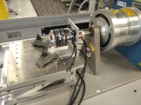
View attachment 1
turnigy 6364 in dyno.jpg

Ok guys I'm getting closer to running this prototype through some tests. Hopefully I can conduct the test Monday. The messy components underneath the controller are the tacked on RC snubbers. Not ideal but I think it will be fine. The heat sink is just an aluminium bar so nothing fancy. Air will most likely be still. Conditions will most likely be better during actual use in an ebike/esk8 with airflow and such. This will at least provide a base line reference to see what we're dealing with. I may test again with an updated version of the controller with an aluminum enclosure and air flow. We'll see how much time I have. Still gotta finish a couple of things with the setup and then it will be time to FOC that motor up.

FYI I've changed the name of my controller to the Cheap FOCer since the word "VESC" is copyrighted...or something.
 
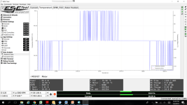
cc51bb926b13e003a9debd4218664ff4acc0a8ba (1).png
I Motor = 20A


View attachment 2
I Motor = 30A


View attachment 1
I Motor = 43A

Completed some initial tests at 24V to 27V. The current to look at is I Motor (Phase amps). The temperature to look at is T FET. This is the current that the MOSFETs pass to the motor and therefore cause the heating. The motor was ran at 18% duty cycle in BLDC control mode. Each current limit was tested for at least 3 minutes or until the MOSFET temperature stabilized.The conditions weren’t ideal with the controller sitting in still-air with only a relatively small amount of aluminum for heat sinking. Real life conditions with most likely be much better when the controller is in a full aluminum enclosure with wind rushing past it as you ride down the road/sidewalk. Overall this gives me confidence that this controller can handle 40A to 50A continuous for a decent duration when placed in the mentioned ideal conditions.

Understand that I am testing continuous current limits. This means that you can still deliver higher phase currents to your motor for a short duration such as for accelerating.

I will do loaded tests at higher voltage levels later this week to see if this can handled the coveted 12s battery.
 
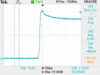
TEK0000.JPG
Vsupply = 50.4V, I Motor = 46A continuous

So I did a test at 50.4V with the motor under load. I picked up spikes of 61.6V under these conditions. Note that I could not use low-induction/low-noise measurement techniques as I did before for this test. I estimate at least 3V are attributed to the non-ideal measurement. Secondly, this is with the bad layout of my prototype. The tester’s edition and beyond will have much better layout and probably lower spikes. I will test the newer version of the Cheap FOCer under the same conditions so a side-by-side comparison can be made.
 
shaman said:
TEK0000.JPG
Vsupply = 50.4V, I Motor = 46A continuous

So I did a test at 50.4V with the motor under load. I picked up spikes of 61.6V under these conditions. Note that I could not use low-induction/low-noise measurement techniques as I did before for this test. I estimate at least 3V are attributed to the non-ideal measurement. Secondly, this is with the bad layout of my prototype. The tester’s edition and beyond will have much better layout and probably lower spikes. I will test the newer version of the Cheap FOCer under the same conditions so a side-by-side comparison can be made.

That looks like a pretty good turn off, no ringing, no spiking overshoot. As long as your peaks aren't exceeding 80% of the MOSFET max voltage, it should be ok. Good practice is to leave 20% overhead, so a 100V MOSFET would not be run with any peaks higher than 80V. You want to avoid putting the MOSFET into avalanche (where it acts like a zener diode) as the energy disspation can get high quickly if it happens repeatedly.

Did you happen to notice the percentage of turn off overshoot dropped when you increased Vbus? I always saw a large reduction in overshoot if I went from 24V bus to 96V bus (using 150V parts). At 24V I could have 48V peaks, but at 96V I could have only 10V of overshoot(106V peaks). I found the most important thing is to avoid ringing at turn off (and turn on).
 
Yeah I looked into the avalanche event of MOSFETs and even posted about that on the previous page. I'm aware of the "80% rule" and I generally adhere to that. However this was the exception. The MOSFETs and DRV8302 have an abs max of 60V. Running it with a 50V (12s) supply is really pushing the limit but this is how some eskaters operate the VESC-based designs. The RC snubbers pretty much eliminated any ringing.

I noticed that current drawn affected that magnitude of the spikes more than anything else. This makes sense being that the spike is a reaction to parasitic inductance which in turns increases in severity when there is more current involved.
 
shaman said:
I noticed that current drawn affected that magnitude of the spikes more than anything else. This makes sense being that the spike is a reaction to parasitic inductance which in turns increases in severity when there is more current involved.

That is expected, but take a look at what happens when you run say 20V bus vs 40V bus and draw the same current. What I've seen in all my designs is the overshoot goes down at the higher DC bus. I've had some designs where this is dramatic. Something like 30V overshoot at 20V DC bus, but then only 10V overshoot at 100V DC Bus. Same pulse width.
 
Kin said:
Personally I don't agree that surface mount fets are significantly more difficult to replace than To-220. Maybe harder to heatsink though.

Key to surface mounts though is knowing the right technique and having the right tools. I can do a lot more at work because we have very powerful & responsive metcal irons. We also have good hot air sources. Combined with general "think about the surface tension" techniques for smaller components, surface mounts are relatively easy.

Designing your own boards though you need to sometimes take special steps. For example, a surface mount fet might have an AxB size pad, but I will make it an (A+1mm)xB pad in order to get contact to the metal pad with a soldering tip. Or, go from underneath with a small hole that you fill with solder to conduct heat from the bottom. Non-standard pads and the like to think about assembly.

A place like oshstencil.com or elsewhere is a great source for kapton stencils. Even in small board numbers it can be easier to use a $10 dedicated electric range and a hot air iron (for the local touch application of heat) to reflow a board.


Overall I appreciate a lot design consideration for serviceability, but just wanted to make a small plug for consideration that surface mounts are not all that bad with a few techniques and small pad design considerations.

If you have trouble desoldering a surface mount chip, especially if the pads weren't designed for solder tips and you don't want to reflow the whole board, then 'chipquick" is amazing shit. it produces a eutectic with the existing solder and dramatically reduces the melting point. Then you clean up the solder with a wick, apply a ton of regular solder (to scoop up any remaining of the chipquick) and remove the regular solder and resolder.
________________


My comment above is a little long winded and indirectly relevant to conversation in this thread. Just want to add more on topic, I like this topic and can't wait to see how it goes! I am hoping to work on a personal project this summer that takes 6 hoverboard motors to run :p. I would love to leverage the VESC platform, but the current costs for 6X vesc (or 3X dual vesc) are pretty damn high. I'm hoping to see how this goes and whether the price with assembly or without ever gets more manageable.


The SMD parts on datasheets look so good they sure are tempting. The problem in high current density designs is PCB trace thermal management. Adding in the thermal load of the dice passing the current to this already thermally constrained trace and you've got a pickle on your hands for cooling. A metalized base (aluminum) PCB helps with the cooling issue, but limits the number of trace planes available and may be a big cost hit done with thick traces. For this reason, the through-hole parts that gets the dice heat load into a different area than the PCB lets that PCB run at higher current densities, and/or enable longer component life from reduced die temp.

https://www.digikey.com/product-detail/en/infineon-technologies/IRF100P218XKMA1/IRF100P218XKMA1-ND/8627116

That part is something that made the Infinion buying IR cut. It has a pretty low gate charge for it's RdsOn and reasonable package thermals.
 
We already beat up poor Kin on the thermal disadvantages of SMD FETs.

Those TO-247 FETs you linked have some really good specs but they'll do some damage to your wallet. Paralleling TO-220s is cheaper but they end up taking up more space. Spoilers here...my next gen FOCer controller will actually have two versions to accommodate either 6 TO-247s or 6 TO-220s. I may go ahead and throw in a 12 TO-220 version too. 95% done with layout in KiCAD. Will be creating another thread for that.
 
I love you all keep it up, I deserved that for my rant. Idk what I was going for but appreciate the honest and clear responses. It's weird both times (as in including now) I'm posting after a run and a little too much endorphins/excitement in my response.
 
ypl said:
drv8302 is not good

Care to expand on that? It's not as good as other solutions these days thats for sure. It's an older device and sucks in comparison to more modern versions like the DRV8323 or the higher voltage DRV8353.
 
shaman said:
ypl said:
drv8302 is not good

Care to expand on that? It's not as good as other solutions these days thats for sure. It's an older device and sucks in comparison to more modern versions like the DRV8323 or the higher voltage DRV8353.

My vesc used discrete drivers and amplifier.It's cheap and stable.
 
Cool. I've considered doing that but I think I'm going to save discrete drivers for high power designs. I also like how compact the DRV8353 is as a solution. I may do something like the BESC but one that can handle a bit more current. It depends on if the designer open sources the BESC design.
 
ypl said:
My vesc used discrete drivers and amplifier.It's cheap and stable.

That's really neat and but has jack all to do with the original question, why is the drv8302 "not good"?

Personally I use a TD350E in several designs up to around 25kW, it's old, low cost and very robust (Miller clamp, negative gate bias voltage, 2 level turn off, desaturation detection) especially when setup with properly.

The drv8302 is ok for low power designs.
 
Project Update :!:

Materials have been ordered/shipped for the beta testers. About 15 or so controllers will be assembled and tested in different global locations. We now wait for materials to be shipped and go through customs. Wish me luck!

Also, I've announced my next project here https://endless-sphere.com/forums/viewtopic.php?f=30&t=99152
This controller will be more in the ebiker's territory with max operating voltage of 84V(20S)
 
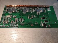
Cheap FOCer in progress.jpeg
Cheap FOCer in progress2.jpeg

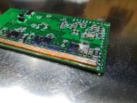
So the person doing the assembly of the Beta controllers is in mid progress. The pics show the solid copper wires being used to beef up the traces. Looks pretty good to me.


Beta batch is coming along! Next is functional testing, attaching the heatsinks, and then applying the conformal coating.
 
So I have good news and bad news.

Good news is that the controllers have been made and are functional in FOC and BLDC(trapezoidal control). My assembler spun a 380kV motor with a 10s battery to test these controllers. No eRPM issues!

Bad news is that I messed up the CAN power rail on the PCB. My intent was to have a beefy automotive grade CAN transceiver to help with the issues people experience when using CAN with HW 4.12. I totally missed the fact that the new CAN transceiver needed 5V and not 3.3V. I didn’t make that adjustment in the PCB design. My assembler is currently getting 3.3V CAN transceivers to put on the controllers so we can at least have functioning CAN for the beta test team

I fixed the PCB design now so that CAN device gets the 5V that it should. This is why I didn’t want to release the design before feedback from the beta test experience.
 
https://github.com/shamansystems/Cheap-FOCer

Ok. So I finally got the GitHub repository up. The schematics and silk screen on the PCB still need some cleaning up on my end but at least this is something. I’ll be cleaning up the files and repository as we progress through the beta testing process.
 
Great work mate, glad to see the project is progressing so well.

Are you planning on open sourcing the design files too later down the line? Or just keeping it at a Gerber's level?
 
Back
Top