First, thanks for the reply and info--even if it sounds later in the post like I'm dismissing some things, I'm not really, and I appreciate all of the response--better to be thorough than insufficient.
")
Jeremy Harris said:
With luck you may not need to reprogramme the controller to run it on a higher voltage. In all probability is doesn't have an over-voltage cut-off, so as long as you can live with the current limit and present low voltage cut-off value you can probably mod it by just changing a few parts.
I'm sure I can live with whatever limits it already has (as I am still going to be using it with the motor it came with, which doubtless can't handle the kind of power it *could* put out at 48V or higher if it didnt' have some sort of current limit).
I would still like to be able to read the settings already in there, and potentially tweak them--for instance, to perhaps even *lower* the current limit from what it is now. If I can't, no biggie, but I've never had a controller that *could* be connected to a PC for tweaking before, and I'm curious enough to want to try.
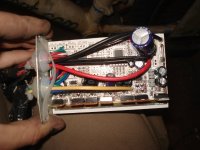
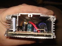
First off, the capacitors on the main power rail look to be 50V ones, so you can't really increase the voltage much without changing them. If you're OK with just going to 48V nominal (probably around 55V peak) then you could fit 63V rated capacitors, if you want to go higher than this then you need to look at fitting 75V or even 100V ones, which may be a problem in that small case,
Caps I definitely know I'll need to replace; I have quite a few low-ESR ones from various UPS units and computer PSUs, and even a few from photo flash units. Some of them are quite large, but might fit even in that small case if left sideways, across the surface of the PCB, between the wires going from the far end of the case to the outside world.
Alternately, I can just move it to a bigger case. I have a few old 2400baud modem cases somewhere that are aluminum, plus a few USB harddisk cases that are also aluminum, and would modify well to this kind of application. I already have a 2QD brushed controller I've been modding to larger FETs and caps, into a former Jensen automotive AC-inverter case (need to get back to that someday for a spare controller for CrazyBike2 if I kill the Curtis).
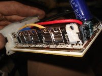
Next, you really need to try and identify the FETs, as it's possible that they will need changing too. I suspect that the FETs you have may be rated at around 60V, so would be just about OK for 48V, but you need to confirm that.
I will probably be changing the FETs even if they are already rated high enough, simply because I already have some around that are almost certainly better than these. There are always voltage transients and spikes in these kinds of applications, and if they are high enough above the "max Vds" they could toast the FETs even if peak battery voltage is actually well within that spec. POOF....
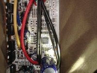
Finally, you'll need to change the big 180 ohm power resistor at the bottom right of the board, the one next to the two vertical capacitors. The value needed depends on the voltage you want to run at, but the values listed in Knuckles Infineon thread should be OK with this controller.
Thanks--that will definitely help.
What I am considering doing is making a self-regulating SMPS of some sort that takes whatever the pack voltage is, from 24V to 100V or whatever, and outputting whatever the LM317 supplies, replacing the entire linear regulator subsystem so I could put any pack voltage on there and test it out with that, not worrying about the power dissipation from that or it's input limitations, voltage dividers, etc. That'd be a last step, though, as it would probably be a fair bit of work to do and get right, even if I start out basing it on the Roman Black two-transistor SMPS.
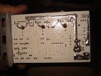
The board could do with a bit of beefing up on the tracks around the high current parts of the circuit, but that's easy to do when/if you swap the FETs out.
True--it's actually already beefed up some with extra thick copper strips soldered to the top and bottom FET traces for D and S lines; you can see this in the pics if you know it's there.
Lots neater than extra solder, and it probably works better, by a bit, too.
In terms of value for money, you may find it cheaper to just buy a 6 FET controller from Keywin. He sells a 48V one, I believe, for around $44 including shipping. It might be cheaper to do this than buy new capacitors and FETs for your existing controller and would certainly be easier.
Easier, sure. Cheaper, no--because I currently don't need to buy anything to mod it, as I already have many things to salvage parts from, and a fair stash of already-salvaged parts.
I did consider buying one of the ones Lyen had in the used section, but I simply don't have the money to spend. (for instance, I only got 4 hours of work this week, same last week, and only 8 hours the week before that).
Plus, what would be the challenge in just *buying* a solution?
Where's the fun in *that*? :lol:
And doing this will increase the store of potentially useful knowledge here on ES, and possibly help someone else down the road.
Also, there's a fair chance I'll end up with blown or otherwise used higher-voltage controllers at some point soon enough, which could replace this one before I even do get to modify it. Still, I'd like to know what to do if I need to.