(EDITED first section after opening box; will attach pics later)
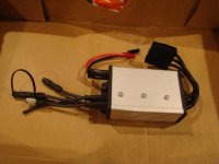
About midday, the dogs let me know the controller arrived, but I'm home sick today cuz I can't seem to stay away from the bathroom very long. :/ Hadn't even gotten to opening the package until a little more than an hour or so ago; took some pics then had to lay down again.
") )
)
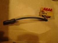
So I'd use the one I have on one end of that cable, and the one you're supplying on the SFOC5 end. I'm using the one I'm using simply because I may need to swap the throttle signal from one controller to the other, either because of a problem or simply for comparison.
Somehow I missed that...I'll go back thru the manual and read it again.
Anything like a dashboard...is probably beyond my abilities. But there is a project here on ES that takes teh Cycle Analyst's data stream and converts it to a tablet or phone display for a dashboard, so it might be possible to use a modified version of that to do it.
FWIW, it's likely that those people running a Cycle Analyst with the Cycle Analogger could use the Analogger to log this controller's data stream too, and perhaps adapt it to log both streams (though I'm not sure how that would be handled; I don't have one to try anyhow).
I'm sure I can figure a way to log both streams of data (CA and SFOC5) on a laptop. If the data is timestamped as it comes in (have to find a program that will do that, I guess) then there should be a way to directly compare moments in time between the two data sets.
About midday, the dogs let me know the controller arrived, but I'm home sick today cuz I can't seem to stay away from the bathroom very long. :/ Hadn't even gotten to opening the package until a little more than an hour or so ago; took some pics then had to lay down again.
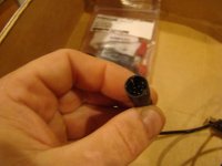
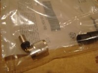
Thanks--I'd assume that's the connector to the controller-box end? (I'll find out when I open the packageincememed said:FYI, a throttle side connector is in the box.
)So I'd use the one I have on one end of that cable, and the one you're supplying on the SFOC5 end. I'm using the one I'm using simply because I may need to swap the throttle signal from one controller to the other, either because of a problem or simply for comparison.
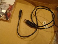
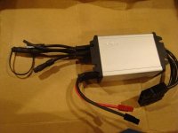
In addition to this, a host of variables (speed, torque, battery current, etc) are transmitted to the Communication port in real time. These can be used for data logging or a more featured dashboard. The format of the real time variables and the communication protocol are specified in the manual.
Somehow I missed that...I'll go back thru the manual and read it again.
That's easy enough,as far as straight logging goes.I have not developed anything around this data, the user or third party must provide receiving side hardware and software.
Anything like a dashboard...is probably beyond my abilities. But there is a project here on ES that takes teh Cycle Analyst's data stream and converts it to a tablet or phone display for a dashboard, so it might be possible to use a modified version of that to do it.
FWIW, it's likely that those people running a Cycle Analyst with the Cycle Analogger could use the Analogger to log this controller's data stream too, and perhaps adapt it to log both streams (though I'm not sure how that would be handled; I don't have one to try anyhow).
I'm sure I can figure a way to log both streams of data (CA and SFOC5) on a laptop. If the data is timestamped as it comes in (have to find a program that will do that, I guess) then there should be a way to directly compare moments in time between the two data sets.