Hall Sensors'b'Gone

PROGRAMMING / USER FRIENDLINESS

Some experimental results, and some thoughts:

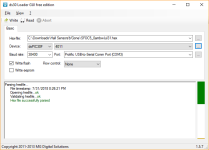
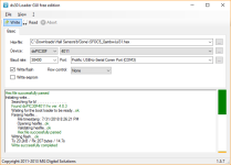
My switch-in-the-tx line doesn't do what I expected. It does make the SFOC go into or out of programmer-connected mode (1 on the status LEDs), when switched to the resistor to hold the TX line high and disconnected from teh USB, it's out of that mode, but it shows status of 9, and when switched back to TX-connected, it doesn't respond to realterm correctly until I:
--disconnect the cable at the SFOC serial port
--power the trike off
--reconnect the cable at the SFOC serial port
--power the trike back on.
At that point realterm will receive and display the last stats, and the SFOC will accept new programming data.

Sometimes, without doing that sequence, just switching the TX line from high to connected, SFOC will receive and echo some characters of the strings sent, but it doesn't do the whole string, and it doesn't send the logged stats, and it blinks error 3 after sending anything.

So for now I will either:

--extend the serial end of the cable, with a connector in it I can completely unplug without getting under the trike,

or more likely:

--use a ganged switch that switches more than one line, once I figure out which ones have to disconnect to totally take it out of any mode that makes it think it's connected. It might be all of them, except perhaps it's TX-out and it's CTS-out. Since the switch I had on hand is a 3PDT (center-off), I can switch the 5v and the RTS lines, too, see what that does. Otherwise I may have a 5PDT switch somewhere. If not, I have 4PDT I can simply add to the switch I already have; won't be totally ganged together, but should still work to switch all the wires connected/disconnected as if I were plugging/unplugging the whole cable without actually doing that.


Otherwise it's quite a task to experiment with settings. :/ (mostly because getting down to the ground and back up off of it for me is difficult, and reachign under the trike to fiddle with the connector to get it connected or disconnected takes a bit of time since I can only do it one-handed unless I lay on the ground; poor planning on my part for where the controller is placed). Each change takes 5-10 minutes to accomplish (out in the heat, which even after dark is still 95-100F+ and 25-40%+ humidity ATM--if it were a "dry heat" it wouldn't be so bad. :lol: ).
 
PROGRAMMING METHOD CHANGE REQUEST

I'd guess that the following could be changed completely in the firmware, without a hardware change, but I don't know how the hardware is setup from serial to MCU.

A much more user-friendly way of getting the stats would be simply having a short "request log" character string the user sends to the SFOC, at any time the serial port is connected, without requiring a power cycle or connect/disconnect/switching. Then the SFOC would send the log data.

Another character string could be sent to take the SFOC out of programming mode and back into normal mode, *or* switching it on at the Status LED panel would do that (as well as power-cycling it).

If requested again in the same power cycle, it sends the same data again, and doesnt' reset teh log data at all while it's in programming mode. This is in case the data didn't make it to the terminal screen for whatever reason. For instance, realterm does not "remember" user-changed settings, so I have to reset them each time I use it. If I forget, like I did the other day on the first real test trip, the log data is then lost. (your upcoming change to make it only overwrite the log data if it's been powered up longer than four minutes might help with that, but if I'm fiddling around with stuff on the computer with it on longer than that, it'd still be lost).


Sending new data would just "work", sending it any time the serial port is connected, even if it requires a power cycle after sending to "reboot" it with the new settings.

As long as the SFOC is "off" at the switch on the Status LED panel, it would then be able to accept or send data as asked.

Whenever the SFOC is "on" at the switch on the Status LED panel, the only thing the serial port would do is send the realtime stats data.

No switches in the serial lines, or plugging/unplugging of things, would be needed.
 
Uploaded (after the usual multiple "gyrations" of connect/disconnect/powercycle/etc :/) the new settings with 0.7 MF an 240A phase, all else the same,

0xF0 0x0F 0x03 0x72 0x16 0xF5 0x00 0xEA 0x03 0xF0 0x21 0xE0 0x0F 0xDC 0x04 0xC3 0x16 0xA2 0x14 0x1E 0x1B 0x44 0x4D 0x59 0x02 0xA8 0x05 0x90 0x1E 0xAE 0x02 0x67 0x02 0x8A

0x18 0x4D 0x17 0x78 0x17 0x0D 0x16 0xD8 0x00 0x2C 0x78 0x4C 0x03 0xA8 0xFE 0xBD 0x3B 0x71 0xCE 0x8F 0x2D 0xEB 0xDD 0xD8 0x1F 0xB9 0x01 0x83 0x00 0x06 0x00 0x00 0xF0 0x0F

and get this log after just offground wheel test
12 34 00 00 00 00 36 D4 39 CA 02 1B 19 90 19 A4 58 15 2F 61 3B B4 39 68 45 2D 04 3D 43 26 14 80 07 C9

Note it says 21A estimated battery, but the CA shows 4.12A peak. will experiment more with that later.


will have more info later after work.
 
and shows the CA doesn't read the same battery current as the SFOC. I don't know which one is correct, but one of them has to be wrong.
Given that operation is still unbalanced, the estimation should not be given credibility at this point.

the new settings with 0.7 MF an 240A phase, all else the same,
I would not bother with any more experimenting with settings before the update. Good thing there is the left motor to rely on;)

Otherwise it's quite a task to experiment with settings. :/ (mostly because getting down to the ground and back up off of it for me is difficult, and reachign under the trike to fiddle with the connector to get it connected or disconnected takes a bit of time since I can only do it one-handed unless I lay on the ground;
Definitely, let's try and get rid of that procedure.

In the light of having 5V from the laptop and to keep interventions at a minium may I suggest you leave the programming cable permanently connected on the controller side. On the USB side, instead of a switch on the TX, you put it on GND (as suggested on p. 12 of the manual). In this way, reading Stats and programming is a matter of

1) Taking your laptop to the switched off trike and connect the USB (keeping it protected with some plastic perhaps when riding)
2) Power on the GND-switch to light up the controller, receive the Stats and do the programming
3) Put the laptop away and power on the Status panel switch to ride

Once logs and programming are less frequent, the programming cable can be removed.

The firmware update
I'm leaving steady code 11 in there, even though it's not in the manual. Pls keep an eye on how it comes on and disappears. (I realise LEDs are not visible in the sun, that's fine, not that critical.)
I'll send you the file tomorrow.
 
I would not bother with any more experimenting with settings before the update. Good thing there is the left motor to rely on;)
At the lower phase current setting, the SFOC5 works pretty well with teh rightside hub once I'm going fast enough...it's the low speed and startups that are difficult. Some better descriptions/etc in another post after this.


In the light of having 5V from the laptop and to keep interventions at a minium may I suggest you leave the programming cable permanently connected on the controller side. On the USB side, instead of a switch on the TX, you put it on GND (as suggested on p. 12 of the manual). In this way, reading Stats and programming is a matter of

1) Taking your laptop to the switched off trike and connect the USB (keeping it protected with some plastic perhaps when riding)
2) Power on the GND-switch to light up the controller, receive the Stats and do the programming
3) Put the laptop away and power on the Status panel switch to ride
Do you mean a switch in the serial side ground, or the usb-side ground?

I assume you mean the serial side, but just in case you don't, some info:

If I put it in the usb-side ground, it will cause windows to redetect the usb-serial adapter as a different instance of the same device, and realterm will first have to be told it's there before it will receive anything. (this is what happened when I tried unpluging and replugging the usb end isntead of serial end to try to save myself a bit of work/time, before going the switch route). Thus realterm doesn't receive the data from the SFOC at power up.

It's part of why I suggested a change to having the user simply send a string of characters to request the data at any time, and not just have it sent at power up/connection time. I don't know if it's possible, but it would definitely make things easier for the user. :)


The firmware update
I'm leaving steady code 11 in there, even though it's not in the manual. Pls keep an eye on how it comes on and disappears. (I realise LEDs are not visible in the sun, that's fine, not that critical.)
I'll send you the file tomorrow.
Thanks! For the LEDs I haven't found my brighter ones, but I am making a little "hood" to go over them to help with visibility a little bit.
 
Notes from the work commute yesterday. I typed them up but coudln't post them last night as intended because a severe thunderstorm and windstorm took out power for about 10 hours, was only restored just before dawn, and I was still trying to get enough sleep in the heat....

I didn't get the log data, screwed up something in the procedure again last night during the storm, and by the time I got it to send the log, it didnt' have the ride data anymore. I didnt' save the log data because it's mostly invalid values like several previous logs (with the CR-LF removed in notepad first).

*********************************

At the lower 240a vs 360a phase current, it's a lot easier to avoid the stutter/shudder; more throttle range exists even at low speeds to do it.

Near the top quarter of my allowable speed range (14-20mph or so) I can now use WOT, which I couldn't before this.

I still can't startup from below around 2-3mph without the pulsing (vs smooth power), and it is still difficult to keep throttle below the stutter/shudder threshold while still increasing it as speed increases (to accelerate as quickly as possible from 0-20mph) so no good comparison can be made between this controller and either of the others.

Even if I can avoid the stutter/shudder, and use the other motor to very quickly (1 second?) get to the startup point for this one, it still takes over 10 seconds to reach a point around 11-12mph that "real acceleration" begins. After that point, I get smooth easy acceleration and ability to push the throttle up almost to WOT (which I *can* do a couple MPH above that now), and it only takes a bit over a second and a half or so to get to 20MPH from there.


Some thoughts regarding stutter/shudder:

I poked around the forum and have seen references to the phase current limits (presumably before saturation) for the MXUS and similar motors being around 200-250A. Is it possible that when saturated, the phase current waveform is distorted in a way that causes the current feedback detection to be unable to read the waveform correctly?

At lower speeds, actual (vs demanded) phase currents for a given throttle setting would be higher due to lower BEMF, correct? Thus, at lower speeds, the throttle threshold to exceed the current needed to saturate the motor would be lower, and cause the stutter/shudder? The threshold would move up the faster the motor is spinning, and so the stutter/shudder would be harder to cause, all other conditions the same?

It might explain why it's behaving better at lower phase current setting, though of course it could be other things too.


I've also considered that it might be distortion or something caused by issues in connections/crimps/solder joints in the motor phase wiring itself, or too small a wire somewhere along the way. I can't remember what gauge the phase wires are past the few inches of 10G or so that comes out of the PP75s, but it's significantly smaller--perhaps a quarter the crosssection. Those are the phase wires the motor itself uses. If it is that, I can upgrade them to some extent, though not a lot without modifying either the axle slot/hole, or adding a second or even third slot (which would let me use 8-10g right from the internal phase connections).

I can look into ways I could modify the motor/phase wiring to eliminate this as a possible issue if you think it could be. Adding two more slots to the axle is the simplest option, and running a separate phase wire out of each slot. Can add the supplied thermistor in with it's own pair of wires at the same time.


Since I'm still using the lower-gauge PP45 battery-charging tap to power the SFOC5, it could also be the battery connection, voltage sag, etc., though the few apparently-valid logs so far might support that, with a sag several volts lower than that at the CA shunt a couple of inches upstream, according to the Min Batt Inst Volt stat. Can fix that with the SB50 connection.


Need to get the realtime logging going. I wonder if there is an android driver for the USB-serial adapter, and a terminal program that will work for this? If so I have an old tablet that I could rig a mount for to see the stuff realtime as I ride, if I could figure out an easy way to "build" an app that can simply continuously read the realtime data and display it as human-readable stats on screen. Maybe the MIT Inventor thingy. Have to look into that. (I'm not a programmer but I understand the concepts...just not good at it).


If everything goes as planned, I have a week and a half off starting this Friday (8-1-18 thru 8-11-18). If not, then it will start the next Friday.

(right now most of what's planned to do then is enclose the back of the trike, and to build the airconditioned trailer for the dogs, or at least as much of these as weather and time permit, plus testing of this controller).
 
Do you mean a switch in the serial side ground, or the usb-side ground?
That's right, serial side (towards USB end of cable, where you put the TX switch, as I understand).

It's part of why I suggested a change to having the user simply send a string of characters to request the data at any time, and not just have it sent at power up/connection time. I don't know if it's possible, but it would definitely make things easier for the user.
The request is noted. Doing so, however, would imply having receive interrupts enabled in the main loop, which goes against the design principle of being dog pound robust.
In any case, the work you are doing now must be facilitated, so if the permanent connection is not viable we'll try some other venue.

I poked around the forum and have seen references to the phase current limits (presumably before saturation) for the MXUS and similar motors being around 200-250A.
Very valuable information for when we start to tweak for that last drip of power that will leave everyone behind at the stoplight. But not the cause of the general dysfunction.

Is it possible that when saturated, the phase current waveform is distorted in a way that causes the current feedback detection to be unable to read the waveform correctly?
Saturation manifests itself as lower inductance (less magnetic bang for the buck), potentially misleading the controller when trying to figure out what part of the voltage is what (bemf, resistive drop, etc.). But it does not address the kind of error you are describing. We may or may not need saturation compensation once we have normal operation. Normal operation meaning at all times in all conditions and speeds up to the 200-250 A you cited operation feels solid and smooth. (For reference, the compensation function is decribed on p. 30-31 of the manual.)

At lower speeds, actual (vs demanded) phase currents for a given throttle setting would be higher due to lower BEMF, correct?
No, they are always 1:1. What would be higher at higher rpm is the voltage the controller must apply to produce this current, having to fight a higher bemf.

The threshold would move up the faster the motor is spinning, and so the stutter/shudder would be harder to cause, all other conditions the same?
You reported this very succinctly some posts ago, which is what I have addressed in the update. It was sent to your e-mail this morning.

Somewhat normal operation in some conditions indicates your connections should be fine. But yeah, let's not close doors.

Looking forward to seeing some longer time series.
 
incememed said:
That's right, serial side (towards USB end of cable, where you put the TX switch, as I understand).
I'll modify it tonight if I can, after dinner. :) However:


Page 28 says that TX pin must be kept low to keep the external device from putting the controller into programming mode. (my mistake there, somehow I got it in my head it should be high when I wired my switch up, so that switch might actually work if I fix it to be a pulldown instead of pullup resistor. :oops: )

So first I'll fix the TX so it's pulled low instead of high by the switch, and test that. If it doesn't fix the issue, I'll do the ground.

Will still need the TX switch to work right, though, so that when using the serial for realtime logging I can turn off the programming mode, right? Well I'll find that out once I get that far. :)


BTW, in a previous post you said:
On the USB side, instead of a switch on the TX, you put it on GND (as suggested on p. 12 of the manual).
but unless I'm just missing it, that isn't anywhere in the version of the manual I have access to.


The request is noted. Doing so, however, would imply having receive interrupts enabled in the main loop, which goes against the design principle of being dog pound robust.
In any case, the work you are doing now must be facilitated, so if the permanent connection is not viable we'll try some other venue.

Ah...I hadn't realized it would entail that sort of change. Wouldn't really want something that could leave a potential for the controller to be "crashed" in-operation by a false interrupt (unlikely to happen, but possible, if I understand the consequences correctly). Even if that isn't a consequence, I expect it would take more time in each loop to check, and lower the max RPM it could be operated at.

This is part of why I'm not a programmer.... :oops:

I also don't want to make anything difficult for you.


Very valuable information for when we start to tweak for that last drip of power that will leave everyone behind at the stoplight. But not the cause of the general dysfunction.
I guess we'll find out what the cause is with enough experimentation. :)

If we can get it working on this trike, it'll probably work on most people's hubmotor bikes, as they won't likely pull this kind of a load at startup/low rpm.


Saturation manifests itself as lower inductance (less magnetic bang for the buck), potentially misleading the controller when trying to figure out what part of the voltage is what (bemf, resistive drop, etc.). But it does not address the kind of error you are describing. We may or may not need saturation compensation once we have normal operation. Normal operation meaning at all times in all conditions and speeds up to the 200-250 A you cited operation feels solid and smooth. (For reference, the compensation function is decribed on p. 30-31 of the manual.)

I'd read that part before, but didn't "get" it until now. :) :oops:


You reported this very succinctly some posts ago, which is what I have addressed in the update. It was sent to your e-mail this morning.
I'll see if I can update the firmware tonight then, so road testing can happen during my commute tomorrow.
 
Well, the firmware update succeeded, using the firmware from your second email that said "this one" (rather than that from the first email with the stats sheet also included) but left me with a problem:

It does not go into programming mode (steady 1 status LED), upon connection of the serial-USB, as it did before.

When the cable is connected (with the switch on the Status LED panel on or off), it only gives flashing 9 error on status LEDs, which is Battery Low Voltage Cutoff. Battery voltage is at present 55v, so is not below what it had been set to for the trike, but may be below the "built in" settings in the new firmware, if there are any.

When the cable is not connectted, with the switch on status led panel off, it gives no code, no LEDs lit.

When the cable is not connected, with the swithc on the status led panel ON, it sequences the LEDs and goes into normal operating mode (hissing) with the code 6 for motor thermal sensor not connected, as normal. (havent' tested actual operation yet)

If I try to update the settings via the statsheet realterm send1/send2 method, nothing is returned back to Realterm after each Send segment, which did happen before the update, so am guessing it's not accepting them.

It does this whether or not I have the battery switched on (i.e., even when just plugged into the USB-serial, so only MCU is powered).

If it is because the firmware comes preset to an 30s battery as teh stats sheet (that came in the email just prior to the firmware) suggests, I don't think I can do anything about it, becuase even at it's lowest allowed voltage by that same stats sheet, it would be over the voltage limit for this controller (over 100v even at "empty" per the stat sheet).

I can try to deal with that by building an 80v battery from some spare EIG cells (or rather, enough cells in series to add in series with the existing battery only at the SFOC5 battery supply port), then see if it will work, using that to reset the settings to my lower voltage 14s "52v" battery the trike uses.

If you don't have any other ideas, I'll try that after work today, as I don't have enough time to do it before I leave for work now.

I have not attempted to reload this version or a prior version of the firmware yet; didn't want to risk corrupting it if this is something that could result in that.
 

Attachments

  • ds30loadergui parsed hex file ok screenshot 080118.png
    ds30loadergui parsed hex file ok screenshot 080118.png
    10.2 KB · Views: 2,046
  • ds30loadergui success write screenshot 080118.png
    ds30loadergui success write screenshot 080118.png
    12.9 KB · Views: 2,046
Good to see we have updates going!

It does not go into programming mode (steady 1 status LED), upon connection of the serial-USB, as it did before.
Odd indeed. This part of the code has no change. The _exit_ from the programming procedure has changes, as per your request. I verified this, and doing so obviously entered programming mode.

This is what it does on startup: First all ports are initialized. Second, it checks a couple of thousand times if there is a TX from an external programmer. If so, it lights up LED code 1, sends off the Stats and waits for the programming string. On the other hand, if no voltage is detected on this pin (which has a soft pull-down), it moves on to continue the startup and eventually enters main loop.

Getting a flashing 9 when powered from the laptop means it has skipped the programming mode (didn't find a TX) and entered main loop, and noted there is zero voltage. (This voltage is always zero to the MCU if LED-panel switch is off, even though battery is connected. They are galvanically separated by an isolation amplifier.)


If it is because the firmware comes preset to an 30s battery as teh stats sheet (that came in the email just prior to the firmware) suggests,
Settings are in EEPROM, program is in flash memory, so the settings you had on the chip before the firmware update are still there. Voltage is a setting and not hardcoded.

Permanent connection of programming cable
To program, as you know, first thing is connecting the USB and telling RealTerm which COM-port to use. The problem if the programming cable is already connected to the SFOC at this point (which is the work-around we are looking to implement to save you from diving under the trike each time) is that the SFOC will send the Stats way before you have finished setting up RealTerm. This can be mitigated by a switch on the GND, so that the controller is only lit up once the USB, the laptop, RealTerm and the user are all in agreement. (Right side of p. 12 goes into why GND can be used this way.)

An alternative to the GND-switch would be for it to first wait for some short special number string that you send once RealTerm is ready.
 
incememed said:
This is what it does on startup: First all ports are initialized. Second, it checks a couple of thousand times if there is a TX from an external programmer. If so, it lights up LED code 1, sends off the Stats and waits for the programming string. On the other hand, if no voltage is detected on this pin (which has a soft pull-down), it moves on to continue the startup and eventually enters main loop.


Getting a flashing 9 when powered from the laptop means it has skipped the programming mode (didn't find a TX) and entered main loop, and noted there is zero voltage. (This voltage is always zero to the MCU if LED-panel switch is off, even though battery is connected. They are galvanically separated by an isolation amplifier.)

Interesting; sounds like a much safer way of doing it than any of the controllers I've seen. :) (bearing in mind I haven't had anything high-end to open up and trace out, so they may do this isolation too).

Regarding LED codes:

I get a steady code 11 (N/A per the manual) alternating every second or so with the steady code 6 (expected), while riding, Status LED board switch ON, under steady throttle for this motor only, cruising just around 20MPH (slightly under/over as the road changes slopes / surfaces slightly).

At a stop, it's just the code 6.

Notes on ride performance in the next post. (it's much better) :)
'


Settings are in EEPROM, program is in flash memory, so the settings you had on the chip before the firmware update are still there. Voltage is a setting and not hardcoded.

I wasn't sure, since the manual advises that after a firmware update, settings may need to be reloaded. (which is waht I was attempting; it's pretty common in devices to have to reset evverything after an update)


Permanent connection of programming cable
To program, as you know, first thing is connecting the USB and telling RealTerm which COM-port to use. The problem if the programming cable is already connected to the SFOC at this point (which is the work-around we are looking to implement to save you from diving under the trike each time) is that the SFOC will send the Stats way before you have finished setting up RealTerm. This can be mitigated by a switch on the GND, so that the controller is only lit up once the USB, the laptop, RealTerm and the user are all in agreement. (Right side of p. 12 goes into why GND can be used this way.)


My problem was that I wasn't really reading that section as applicable, probably because it discusses pin-by-pin connection, rather than the prewired connector. I *should* have, though, because by switching any line, I'm no longer using it as a pre-wired connector. :oops:

At any rate, it doesn't really go into detail about switching lines; just says:

"If connecting pin-by-pin (as opposed to a pre-wired connector), use the following order to avoid the converter TX pin to prematurely power on the Controller:

a. USB-TTL TX -> controller pin 5
b. USB-TTL RX -> controller pin 4
c. USB-TTL 5V -> controller pin 2
d. USB-TTL GND -> controller pin 3

I suppose that could be greatly oversimplified down to say "hook up ground last", and/or "without ground connected as reference other signals are ignored/invalid until ground connected. " which would imply that as you point out a switch in ground line would switch it in and out of programming mode (assuming a valid signal on the other pins already exists). :) :oops:


To be safe, what I tried first was to leave the switch in the TX line (which I had changed to a pulldown rather than pullup) in the connected/unpulled-down state, and use complete disconnection / connection of the serial end of the cable to/from the SFOC, for the firmware update, and the first power cycle afterward. Also did this for the first few attempts after that, all with the reported error.

After those, I tried the pulldown of the TX line, which didn't work, and after some attempts with this, I removed the switch entirely from the equation, reconnecting the wires as they originally had been, and used direct connection as before installing the switch.

I suppose it is possible that I have somehow damaged the USB-serial adapter, which I'll test for next. I have others if that's the case.


Either way, for now I'll just extend the cable on the serial side up to do all this, rather than messing with the switches (simpler, less to go wrong while riding, etc). Later I'll put a switch in ground if it seems indicated.
 
POST-FIRMWARE UPDATE RIDE:

Things are MUCH better now. :)

Keeping in mind that since it does not appear to be updating the settings via the RT send1/2 yet, it is presumably still using all of the same settings values it had before the firmware update, in hte last stats sheet file a few posts previous.

Now I can actually just pedal a slight amount from a stop, a few strokes, and be able to start throttling up at a low enough speed the CA hasn't even begun to give a speed reading (so below around 2mph). This is a huge improvement in low-speed power application; I can almost hit full throttle from there (not quite, though--if I do, I get the same stutter/shudder as previously happened at much lower throttle levels.

It's still a somewhat rough power application at that point, but it quickly gets smoother. I say smooth*er*, because it sort of feels as if I am riding on a lightly-ribbed road surface that gets smoother the faster I go.

I suspect this is caused by pulses of current that may not be perfectly timed, or that are simply large currents pulling the magnets along in pulses. (not sure I'm really describing it quite right).

Partly my suspicion is based on a significantly higher current draw in cruising at various speeds. It's hard to ride and watch the Amps display on the CA at the same time, especially with traffic around, and driveways, etc., but I did as much as I could previous to the updates and would estimate that at 19-20MPH it was taking around 12A at about 54v to maintain that speed. Now (based on much less riding/watching) it appears to be taking around 18-21A at about the same voltage to maintain that speed. Similar proportional increase at lower speeds, but have less observations on both before and after for anything other than the typical cruising speed of 20MPH.

It'll take more observation time and riding in different directions under the same weather conditions on the same roads to verify tha'ts not just an artifact of just today's commute.

The CA shows a definite current draw increase in total, at 129A peak today, vs any of the previous peaks of usually mid-80s, a few just over 100A. We'll see how it does in further rides. I have a work commute again tomorrow, then I should be off for a week and can do a lot more riding to check it out. :)


Oh, and acceleration from a stop with both motors is at least half a second quicker from 0-20MPH than it was before; might be nearly a whole second quicker. It's hard to say exactly because unlike with the grinfineon/generic controller combo running the motors, acceleration does not fall off approaching 20mph, but rather actually *increases*, so I can pass the 20MPH mark before the CA speedo "catches up" and shows me I'm there. :lol:

Because of the low acceleration at low speed (compared to the generic sensorless, or the Grinfineon sensored), the SFOC5 is still not all that quick by itself, but because it has high acceleration at higher speeds it is now at least mostly comparable to either of the other controllers on their own.


The CA stats from today, if they're useful (since I haven't been able to get the SFOC's stats yet).

55.7vstart
53.8vrest
53.8vmin
4.67miles
4.481ah
241.39wh
51.4wh/mile
0.4%regen
0.018ah regen
4.5009ah fwd
-5.4Amin
129.6amax
21.9mph max (oops...accelerates vvveeery quickly once up near 18-20mph!)
14.4mph avg
19m28s triptime
rbatt 0.31ohm
 
51.4wh/mile seems a bit high, but you have a heavy bike. How does that compare with your old controller?
 
It's not a significant difference, though so far it's a bit higher on average (a few percent). With this CA3.1, it shows typically in the 45-55wh/mile range for commute and store trips, stuff with short distances and a lot of stops, so lots of power usage in accelerations and brakings (since the left side controller uses some power to brake, rather tahn regenerating it).

(with the older CA 2.4, same shunt, same shunt settings, it showed something around 10wh/mile higher, but that' a mystery for a different thread :lol: )


Due to a few problems with somewhat critical household stuff caused by the long power outage and/or the thunderstorm, I didn't get to trying to test with a different USB-serial, or extending the serial cable on the SFOC5, last night. Am off to work in a bit so won't be able to do that till tonite or tomorrow at this point. (and still have a few household things from the storm to fix like the washer).


Even without further changes, the controller is now at a useful condition, and if I could upload settings I'd probably try out the braking option (where throttle rollback below present current demand would brake the wheel).

Still needs a bit of work / settings exploration for low-speed smoothness and acceleration. Could be that upping the phase currents back to max would fix the latter, but it'd probably also make it rougher. Have to try once I figure out the serial-usb issue.


The one thing I wish could be gotten rid of, or at least really really toned down, is the low-frequency rumble/vibration the controller's position/etc sensing causes the motor to induce into the trike frame. If it were only during acceleration, etc., it would be acceptable, but because it is present at all times and the same amplitude, the SFOC5's status LED panel switch is on (and thus the controller operating), it's very annoying.

Imagine running white or pink noise thru a subwoofer and sittingg on it while you ride, with the volume up a fair bit. :) If there's enough wind noise you can't hear the hissing part most of the time, but you can always feel the low frequency parts, unless the road itself is pretty constantly rough (gravelly-feeling?), in which case it's drowned in the road bumps and vibrations. :/ Not that much continuous road surface like that around here, thankfully, though there's patches like that.


Nothing to be done about it, though, other than rebuilding the trike frame to separate the motor mounting section from the rest of the frame with vibration-damping between them. Something unlikely to happen anytime soon, though I can imagine the way I might be able to do it.

It will be interesting to compare this controller to the Lebowski design, once I finish one of those. I wonder if it also has the same hiss and vibration/rumble?
 
What kind of parameters in a control loop would potentially cause that? There might be some I can tweak in the stats sheet (once I fix the serial problem).

Bit more ride info from the trip home from work last night (in the rain):

Since the streets were nearly deserted because of the intense windstorm prior to the rain and thunderstorm, I was able to (carefully and slyly ;) ) do some acceleration tests beyond the usual 20MPH.

I went ahead and held max throttle after reaching 20MPH, and was at almost 26MPH about one second later. :shock:

Because of the wet roads, I didn't continue past that speed (braking distance would be too long if something did require a quick stop, without the righthand wheel regen braking I'd usually have from the Grinfineon, and I don't have braking enabled on the SFOC5 yet), but I imagine that it would have continued accelerating quickly to whatever the potential top speed of the trike is (which I don't know).


Now, if I could get that kind of acceleration at low speeds, I'd be *really* impressed with this controller. :)
 
SERIAL CONNECTION ISSUE FIXED

Short story long:

Today I noted down colors of the four wires from the supplied usb-serial adapter to the four used pins of the 5pin round male that connects to the SFOC5 end of things, then desoldered these. Then I cut an old serial cable's male end off, and soldered up the about-6-foot-long female end to the 5pin round male for the sfoc end of the serial cable. (not the one that is wired into the controller, but the one that plugs into that).

That extends the serial connection out to make it easily reachable.

After that I spent a few hours of testing/troulbeshooting another USB-serial adapter (which has 0-5v serial I/O like the supplied USB-serial adapter), verifying wiring, continuity of the extension cable used, etc etc. Because this adapter doesnt' naturally run a 5v power line out, as it uses the normal DB9 output and wiring, I disconnected the DSR pin from the PCB of the adapter, and wired it to the USB's 5v, then used that wire from the DSR pin on my extension cable (an old serial cable with the male end cut off) to supply the 5V to the SFOC5's com port. At one point I even swapped RX and TX to make sure I had them the right way; no change.


The adapter does work with a couple of other really old serial devices I have laying around, without the 5v/dsr line modification, so there is some other issue than a defect in it. Probably something stupid I'm overlooing.

Results were slightly different, but I still couldn't get programming mode out of it, or get a log, or send data, or get realtime stats. The Status LEDs would only continue to blink code 9.


I looked at my other USB-serial adapters that i knew where they were at, and the Belkin DB9 unit wont' work because it's a -9v to + 9v output type, not compatible with the SFOC5. The GrinTech adapter just has ground, TX, and RX on the 3.5mm phono jack it uses as a serial end, so i'd need to run a separate wire for the 5v line, after hacking into it's USB shell to get to the line. (or using a separate USB plug to get a 5v tap off the other USB port on the laptop). And I'd still need to make a converter from the phono plug to the DB9 I want to use for the extension end.


More work than I wanted to do yet, so I went back to the original supplied usb-serial adapter, and began checking it's wiring and signals. The first thing i found was that the red wire, the 5v line, has a break inside it's insulation a couple of inches away from the end that used to go to the SFOC5 round connector. Held just right it connects, otherwise it is open. The rest of the wires are ok.

So from there I soldered up the leftover male end of that serial cable to the board of the originally-supplied USB adapter, completely replacing all the wiring from it's serial side, and now that adapter works fine.

Go figure.


Anyhow, now I am able to get the power-up stats, and send the RT1/2 data, as well as see the realtime output when the Status LED panel switch is on.
 
Now that that is working, I sent the RT send1/2 data created using the new stats sheet sent along with the firmware update, changing the motor parameters, battery and throttle settings to match the trike, and the battery current limit to 140, phase to 250, rpm to 680 (to keep it in the limits for my lower battery voltage). All else including all blue fields left as-supplied.

Ride tests to follow in a bit, after I've cooled off some (its' only 111F out there so not as bad as it has been, but hot enough).

This is the RT1/2 data
0xF0 0x0F 0x03 0x5B 0x16 0xD3 0x00 0xF0 0x03 0xEA 0x1D 0x73 0x17 0x1F 0x0B 0x54 0x16 0xF3 0x14 0x1E 0x1B 0x44 0x50 0x5C 0x02 0xA8 0x05 0x90 0x1E 0xAE 0x02 0x5A 0x0C 0xCC

0x18 0x75 0x17 0xB4 0x17 0x53 0x17 0x23 0x00 0x33 0x79 0x28 0x03 0xCD 0xFE 0xB0 0x3B 0x71 0xCE 0xD8 0x2D 0xA7 0xCE 0x35 0x2E 0x3E 0x01 0x7B 0x00 0x06 0x00 0x00 0xF0 0x0F

and the stats sheet itself
 
REALTIME STATS MONITORING

I've been looking into how to read and potentially display the realtime data in a human-readable way, but I must be missing something, or am just being stupid again. (happens sometimes, where I miss the obvious because I don't think like most people).

AFAICT, there isnt' any "1234" header in the data to tell where each set of stats starts. (i.e., the powerup logged stats that use 1234 to designate the start of the "phrase"), however there may be a different header; for example in the captured data I got in a quick check of the capture function there appears to be one of "F00F", but it's not specified in the manual in the data logging / dashboard section.


Without knowing for sure what the header is supposed to be, a program reading the data cant' figure out where to sync up from, if the serial data stream either gets its' first part missed, or glitches at the input of the reading device for wahtever reason, etc. I'm posting about this stuff ATM because I'm trying to learn enough about the android stuff to use a tablet and ti's external usb adapter to read the serial port and display the stuff, in this thread over here:
https://endless-sphere.com/forums/viewtopic.php?f=30&t=95633


For instance, this is the powerup stats from right after I got the serial connection working again:

Code:
12 34 7F FF 00 00 7F FF 00 00 00 0C B0 8C 00 00 01 FF 01 9F 03 9E FD BD 00 C7 17 1A 17 1A 00 00 00 00 00 00

This is a sample of captured serial output from the realtime stats, created by setting RT to capture to a file, starting the capture, then switching the controller on at the Status LED panel switch, parsed by using the F00F as a header:
Code:
F00F000000BD00AC00001840000042E9000008401508
F00F0000FF87FE3900FF1A80000042D7000008401505
F00F0000FF1E00C500FF1A80000042D8000008401514
This is the full capture file, unparsed
View attachment capture 080318 1.txt


If I am parsing it correctly, then the first line would be
F00F 0000 00BD 00AC 0000 1840 0000 42E9 0000 0840 1508
and split up would be (ignoring the F00F header)
Reference torque = 0000
d-axis current = 00BD
q-axis current = 00AC
Battery current = 0000
Battery voltage = 1840
Speed = 0000
Heatsink temperature = 42E9
Motor temperature = 0000
Status = 0840
Throttle input = 1508

Just at a glance, the zero and low hex numbers look like they're in the right spots, for just sitting there powered on with Status LED switch on, no throttle usage, wheel off ground, without referencing any of the formulas in the chart.

Assuming I'm using them right, then using the formulas in section 13 of the manual page 28, I get these values:
Reference torque = 0A
d-axis current = 2.98773193359375A ***
q-axis current = 2.718994140625A ***
Battery current = 0A
Battery voltage = 60.673828125V ****
Speed = 0RPM
Heatsink temperature = between 45C and 50C (value 17129) *****
Motor temperature = 0000 (no sensor connected)
Status = 0840 (Not sure; note for this is a bit confusing.)
Throttle input = 0.821533203125v ******

I think i'm doing the conversions right: for instance, the torque and current conversion formulas are 581a / 2^15 units. That would imply I should divide 581 by 32768, then multiply that result (0.01580810546875) by the decimal version of the hex values. Similarly with teh battery voltage, 285 / 32768 * the decimal version of the battery stat (which comes close enough to make me think i'm right).


*** i guess this current accounts for the constant wiggling of the wheel and the drag it has just sitting there off ground, and the vibrations in the trike..but doesnt' explain the zero battery current)

**** This is close; should show 57.5v, which is what I read at the CA and at the battery input connector.

***** probably about 115F, which sound about right, given the 111F air temperatures, and the sun shining on the ground heating it up then that heating the controller under the trike a few inches above the hot ground.

****** This is close, is actually 0.89v throttle input at zero throttle, measured at the connector just prior to entering the SFOC's throttle connector.
 
Example video of the jitter / wiggle of the offground wheel, no throttle input. Also includes example sound of just how loud the hissing is; you can hear it over my voice narrating directly into the camera mic from a couple of inches away, and a pretty loud helicopter or airplane flying somewhat low overhead, as well as Kirin's panting a few feet away, all happening at the same time.

Can't really hear the low frequency part even with the camera resting against the trike frame, but it's there, too, and just as "loud".

https://www.youtube.com/watch?v=4Sx4wzgVlgU

[youtube]4Sx4wzgVlgU[/youtube]

I apologize if it seems I am harping on this particular thing, but I want to be sure to get across the level of sound/vibration being emitted as it seems very unusual. I have no experience with any controller that does cause a motor to emit sounds/vibrations when not actually spinning the motor, so maybe they're all this loud, and vibrate their vehicles, and maybe they all make the motor wiggle back and forth like this when not held in place by vehicle weight.
 
Anyhow, now I am able to get the power-up stats, and send the RT1/2 data, as well as see the realtime output when the Status LED panel switch is on.
And without having to reach under the trike, I assume. That's great.

REALTIME STATS MONITORING
The F00F is indeed a header, it's just I'm lagging behind in updating the manual. Also, full range of current is 646 A, not like in the manual.

I apologize if it seems I am harping on this particular thing, but I want to be sure to get across the level of sound/vibration being emitted as it seems very unusual.
The default PI-loop gain parameters are too aggressive coming out of the Settings&Stats, let's see if we can work our way to more suitable default parameters.

You are now using Multiplication factor 1.0, as per your settings sheet. I would like you to walk this down towards a level you are comfortable with, while noting any changes in responsiveness. The step response plots some page back serve as guidance. For example, we can see that the second plot (MF=0.5) looks almost identical to the first (MF=1.0). The third (MF=0.1) is clearly much slower, but the time frame of the plot does not let us see if it is stable.
 
incememed said:
And without having to reach under the trike, I assume. That's great.
:) Yeah, with the serial-side extension, it's long enough I could now put a device on the handelbars to read the stats, if I can make one (trying to figure that part out; could be a while :lol: )

The F00F is indeed a header, it's just I'm lagging behind in updating the manual. Also, full range of current is 646 A, not like in the manual.
At least I'm not as bad as I thought I might be. :)

Speaking of updating the manual, I noticed that it appears to be in flattened "image" format in the PDF, vs a text format. If there's an unflattened version that I can copy/paste from to suggest edits without retyping it all, it would be helpful. :)


The default PI-loop gain parameters are too aggressive coming out of the Settings&Stats, let's see if we can work our way to more suitable default parameters.

You are now using Multiplication factor 1.0, as per your settings sheet. I would like you to walk this down towards a level you are comfortable with, while noting any changes in responsiveness. The step response plots some page back serve as guidance. For example, we can see that the second plot (MF=0.5) looks almost identical to the first (MF=1.0). The third (MF=0.1) is clearly much slower, but the time frame of the plot does not let us see if it is stable.
Ok. I'll try a series of values tomorrow (today, actually, but after I sleep ;) ) and see what happens.

FWIW, with the previous firmware, when I tried an MF range of 0.5 thru 0.7 thru 0.85, it did not appear to change the hiss or vibration of the system when not actually using the motor (or when at a standstill, etc). Hopefully it will be different with the new firmware. Or else I was just not going far enough with the setting; I guess I can start with the 0.1 and work my way closer to 1.0.


I suspect part of the issue is that this motor is physically larger with more copper and magnet to move around than the RC motors, so it magnifies the noise much more. Being affixed to the trike frame via the axle probably also does this. (vs the possibility of "soft" mounting methods that could be used with RC motors of some types, that could absorb some of this noise and vibration).
 
Changed MF to 0.1.
View attachment Experimental settins 08-01-18 01 Settings&Stats SFOC rev 5 pub 7-31-18 version.xls

HUGE reduction in the noise; vibration is gone, and the hiss is now a whisper so quiet Id have to be indoors in a quiet room to hear it without my ear to the motor. :)

So--THANK YOU for that. :)


The only effect on riding appears to be to make it easier to maintain a stable speed without much throttle movement. Not even sure there's a difference there, as it was already easy enough.

Low speed acceleration appears the same (not nearly as good as that at near the top of my allowed speed range of 20MPH), although I'll have to experiment with MF values to see if it's causing the stutter/shudder if I hit WOT from a near-stop rather than rolling on throttle (I'm still used to WOT from a stop as used on the generic controllers).


Wheel does still have the detent-feeling at a stop, if I attempt to roll forward on pedals or hand turn the wheel; this is about the same (without a numeric test I can perform for it, like a torque wrench value. One possible description is that the diffference between the controller off and the controller turned on but no throttle is about like the difference between a completely freewheeling well-maintained bicycle wheel, and a really heavyduty motorcycle-sized DD hubmotor.

Once I start it spinning, by hand offground or rolling forward by pedals, it's much much less but still a bit present (maybe a quarter or ten percent of what it is at a stop?).

Hand-spinning it backwards it actually gets a bit harder to move. Can't pedal backwards so no comparison test possible there.


Quick ride down the street and back gets the following stats results:
080418 1 stats.png

and capture log:
(hmm...this file seems to be missing)


Ride test for around 5 miles with good results. Accelerations and such are similar to or the same as before changing MF from 1.0 to 0.1.

I still see the code 9 alternating with the code 6 while riding, but only the code 6 while stopped.

Will have the ride stats in the next post (or edit into this one later); forgot to get it before coming inside; still cooling off before I go back out and get it. (it's only 107f in the shade but humidity is over 30% and in the direct sun it's probably 10-15F higher)


SFOC5 is definitely reading the battery voltage a bit higher than it actually is. I am not sure if it's a scaling or an offset error yet. Have to compare the voltages when I've run the battery down a bit to see which it is.
'
Ride stats to this point
12 34 00 00 04 21 3D C1 58 31 02 9A 13 FF 1A 51 39 BC 33 2C 37 91 16 18 39 BC 00 00 69 C6 B5 20 24 B0 23 B8
ride stats 080418 half 1.png

Attached is a long captured logfile from what should be the entire ride from my driveway to parking here, but it's very short, so either:
--capture failed somewhere along the way
--capture failed to start at all and this is the file that should be above from the down-the-street-and-back test.

I'm still trying to figure out how to write something to take such a file and parse it into a human-readable log; it's not something I've ever done so might take a bit of time. :)
View attachment 3

Takes me several minutes per log entry to convert by hand (me and math don't get along), so I didn't convert any to post.
 
Second half of the ride about the same, some other observations and some logged data.

Now-silent operation and standby is GREAT. :)

Except that I am still getting used to controlling speed by feel rather than motor sound. :oops: However, it is easier to hold a speed with the present setup of SFOC5 than it is with just about any of the other controllers I've used, even when I've used the CA's current-throttle to control their speed-based throttle input. (the CA is not in the control loop at all presently).

Cycle analyst peak amps is 129, battery voltage started out at 57.5v, ended at 53.4v Sagged as low as 53.1v. 10.9miles total round trip. 51.2wh/mile.

Was pretty windy coming home, about 3 hours after I started out (stopped for lunch halfway). All the riding into the west was against a 20MPH-ish wind.

Tested loading on SFOC5 / MXUS 4503 vs Generic / MXUS 4504, cruising at 20MPH against that wind; SFOC took right at 12.1A to maintain that (at 54V), while the Generic took 13.5A. (per the CA display, battery current). Could be the difference in the motor winding (3T vs 4T), or could be the sine vs trap drive, or other things, or a combination.

WIthout the wind (after it died down and I could ride along a windbreak area in a direction cross to the wind) it's about 10A for SFOC and 11A for the generic.


Stats for the ride back,
12 34 00 00 02 3D 4C 4C 58 B8 02 5B 18 3E 18 CF 41 89 41 C1 3D 78 21 4E 42 AC 14 22 68 22 13 60 24 42 22 B1
View attachment 1


and the realtime capture log (shorter, as I stopped at Goodwill and forgot to restart the logging afterward).
View attachment capture 080418 2.txt
 
:) Yeah, with the serial-side extension, it's long enough I could now put a device on the handelbars to read the stats, if I can make one (trying to figure that part out; could be a while :lol: )
There are three fundamental elements here: UART-communication, arithmetic and displaying on generic LCD. Maybe something for a final project in high school or college introductory embedded course.

Speaking of updating the manual, I noticed that it appears to be in flattened "image" format in the PDF, vs a text format. If there's an unflattened version that I can copy/paste from to suggest edits without retyping it all, it would be helpful. :)
Sure. Didn't see any suitable option in the Word Save as PDF dialogue, though. (I was able to copy/paste from the PDF.)

Stats for the ride back,
There was a 90% overshoot at one point (Max Iq vs Max Iq ref) in your last post. While this may have little effect on the perceived torque overall, it is not ideal. With that big of an overshoot if demanding close to rated current, the Power down function will activate.

I suspect MF=0.1 may be on the low side. But let's not rule it out until the low speed WOT stutter has been fenced in. Stutter at WOT from zero/low speed sounds like an R or L issue, rather than kv or MF.
 
Back
Top