Hall Sensors'b'Gone

Measuring phase-to-phase resistance of a motor is simple. Just put a known current through one phase and out of another. Measure the voltage drop, and calculate the resistance.

For inductance I just use one of the bare-bones inductance meters I picked up on Ebay for under $20/ea.
 
John in CR said:
Measuring phase-to-phase resistance of a motor is simple. Just put a known current through one phase and out of another. Measure the voltage drop, and calculate the resistance. It's always good to measure all 3 ways and compare...to make sure there aren't any broken or inadequately soldered magnet wire strands on any of the phase windings.

For inductance I just use one of the bare-bones inductance meters I picked up on Ebay for under $20/ea.
 
If I had some Kapton tape, the magnet wire's what I would have done (because I recall at least a couple of people doing that sort of thing in various motor-upgrade threads years back). (I'd also probably hard-anodize all teh surfaces the wire might contact)

What I'd really prefer to do is the larger-ID-bearing and spacer-ring-with-wire-holes inside the ID of the bearing, that both of us have talked about doing before, but I'd have to custom-make a side cover for that, as well as order bearings, etc. IF I was going to do that, I'd also want to do a serious axle upgrade while at it, which adds a lot more work...so I haven't ever gotten around to any of this. Money is another reason I haven't.


The good news is I finally got some (18g) wire thru, teflon insulation, with a second layer of heatshrink insulation over them, and also got a pair of 28g wires out for the thermal sensor, and verified each step of the way with the isolation tester on 250v that it's all ok, including with it fitted into the dropouts, fully tightened down, wires tied down, etc.

Then I tested on the crappy generic 12FET and it works, offground. It sounds normal, feels normal, and no visible or audible rocking of the axle between braking and acceleration. Didn't try onground because I didn't want to roll the trike over and get it out of the shed yet; was too tired to be sure I *could* do it.

Then I hooked up the SFOC5, which is still programmed for the 4504's guesstimate parameters, to the repaired 4503. It does the usual continuous jitter dance, and a tiny bit of throttle begins spinning it up; if held goes faster and faster but begins being unhappy; not unexpected since it has the wrong settings for this winding of the motor.

But at least it "works". Have to take the laptop out there tomororrow and reprogram the SFOC5 to the right parameters for the 4503, and test offground, then onground.
 
John in CR said:
Measuring phase-to-phase resistance of a motor is simple. Just put a known current through one phase and out of another. Measure the voltage drop, and calculate the resistance.
I suppose that's obvious enough I should've thought of that...it certainly sounds familiar.

For inductance I just use one of the bare-bones inductance meters I picked up on Ebay for under $20/ea.
Do you happen to know which model and seller? (so I can be more sure the one I get will actually do what I need it to--there are literally thousands of listings out there, and most of them look very similar, even identical, and they start around $5-10)
 
amberwolf said:
John in CR said:
Measuring phase-to-phase resistance of a motor is simple. Just put a known current through one phase and out of another. Measure the voltage drop, and calculate the resistance.
I suppose that's obvious enough I should've thought of that...it certainly sounds familiar.

For inductance I just use one of the bare-bones inductance meters I picked up on Ebay for under $20/ea.
Do you happen to know which model and seller? (so I can be more sure the one I get will actually do what I need it to--there are literally thousands of listings out there, and most of them look very similar, even identical, and they start around $5-10)

Sorry, I can't remember and no brand on the board. I seem to recall they were $10 or $12 ea, cheap enough that I bought 2. Just make sure you to get one with the right scale. I tested mine against a some air coils I have from my previous speaker building hobby and they seem accurate enough for our needs. For me it's just interesting to know what the phase-to-phase inductance is to get an idea of how hard the motor will be on a controller. Plus, like resistance I like to know all 3 ways to verify that the motor is wound properly.

Back when high power controllers were non-existent, my higher than typical hubbies liked to snack on controllers, so I made 3 toroidal coils using big speaker magnets and 8awg wire to put in line with to protect a controller, which helped it run a bit cooler. The meter told me I added about 100mH. It's nice to not have to worry about that kind of stuff anymore, since my 6 phase motors inherently have greater inductance for the same Kv.
 
I was going to just reply with corrections to my previous post, but there was so much erroneous stuff (because of things I'd forgotten in the time between breaking the motor and fixing it) I just removed it and started over. ;)


Some on-ground testing, after changing the SFOC5 settings to match the previously-known-working 4503 characteristics.

Note that ATM my phase wires are very thin (18g) and very long (3 feet) to reach around from the outboard axle exit to the SFOC5 that's still mounted over on the left side. I can probably take half that length out by moving the SFOC5 over to the right side, if necessary. I have not changed the resistance or inductance values to include whatever these might add (because I don't know if it's significant enough to worry about).

It actually works significantly better than it did previously, likely due to the various changes in firmware in the SFOC5, *especially* at startup from a stop. (which while not perfect, works almost like I'd like it to, when using it with the Cycle Analyst and PAS control (via throttle I'm still working out what are probably just settings issues).


Might be a known issue that I've forgotten about since it's been too long since I was able to do anything with this, but neither stat sheet will accept most values "in range" for torque downramp (output fields give "not valid") max accepted is 0.05.
EDIT: this is still around from here:
https://endless-sphere.com/forums/viewtopic.php?f=2&t=30680&p=1401088
though a post shortly after says it's fixed. I guess it cropped up again?


IIRC this is supposed to be the "negative torque" ramp to allow reducing throttle to force braking? I'll have to go back and reread the thread; my memory is so bad sometimes. :oops:


During a short <2mile test ride around the neighborhood, there were a few problems, but I determined they were caused by operator error in one case (forgetting to change the throttle range settings) and one of the "new" settings in the toher cases.

The new setting is the Startup Pull (RPM), which defaults to 60. At first, I left it at that, just to see how it might work at that value. This would cause hammering, presumably as the field was not synced with the rotor; it felt like the motor trying to pull back and forth at a little more than a tenth of a second for each hammer (hard to judge stuff happening that fast). Hammering only happened at slow speeds, 4-5MPH or less. But it wasn't useful for it's intended purpose, of helping to start from a stop.

I changed it to 100, but all this did was to increase the speed at which hammering stopped to around 7MPH, and I think it increased teh rate at which it occured to les than a tenth of a second apart. Hard to be sure.

I tested the transition point by speeding up with the other motor system (generic controller / 4504) to about 15MPH and coasting down, applying throttle to SFOC5 / 4503 system in blips as the speed decreased, until eventually it would drop to a point at which it would hammer when I blipped it.

Then I set Startup Pull (RPM) to zero, and the hammering did not occur, presumably because this value means SFOC isn't trying to just rotate the field "blindly" at all (to force the motor to start turning). Interestingly, not only did it stop the hammering, but it also meant that using the Cycle Analyst PAS torque sensor to control throttle actually let me startup smoothly and powerfully, if a bit slowly (but I only have phase amps set to 150 right now, and some of the CA PAS tuning is set to lower values as well). This is starting up in my "middle" gear (the highest IGH gear and the lowest crank gear, which gets me about 5MPH or so, on pedals alone).

I was enjoying this new ability so much that I did not remember to test throttle-only operation once I set it this way. :lol: :oops: It was like I had bionic legs; almost the way I would really like it to be (the rest of it is tuning the CA to match the abilities of SFOC5 and then I think I might have it!).

I'll have to go back out and test that in a bit, after lunch and this write-up of results.

Note that on a sensored Grinfineon "40A" 12FET or a sensorless generic "30A" 12FET, also controlled by the CA PAS, it's quite difficult to startup from pedalling alone, even in my lowest overall gear (which gets me about 1MPH or so, on pedals alone). On throttle those same controllers startup ok if I use WOT, but they don't have much power, especially compared to the SFOC5.


For the moment I have the thermal sensor hooked up to the Cycle Analyst, and just displayed it's output onscreen (in place of the Ah / Distance reading that toggles between those values, for now), so I could watch motor temperature go up and down with use. Peak was around 50C, dropping down to 45C within a couple minutes after stopping. Ambient (and motor starting temp) was 24C at the time.

Once I (re)learn how to setup this sensor (I think it's a KTY83/110?) in the stat sheet I'll hook it up to the SFOC5's input instead, so it can do it's thing protecting itself and the motor from overheating, while I abuse the system testing it. :) I"m pretty sure I had this figured out at some point and just forgot.


Ride data from one of the smooth trips around the block will come after lunch.

Ride data from a hammering ride:
150a phase 100rpm startup pull
12 34 7F FF 00 00 32 96 3E 67 01 67 17 55 18 1D 29 6E 27 E4 2A 94 16 1F 2A FC 00 00 75 16 15 8B 15 D4 1D B7

An earlier ride at
100a phase 60 startup
12 34 7F FF 00 00 2F A4 38 8F 02 2E 18 1E 18 3D 10 CD 0F A2 10 EF 10 65 10 45 14 57 72 AB 17 B6 0A 9B 13 CF

Attached the current stat sheet.
View attachment Experimental settings 030519 5a Settings&Stats SFOC5 20190303.xls
 
incememed said:
It appears that ebikes.ca uses something close to 9.2 in their simulator for the HS3548.
https://www.ebikes.ca/tools/simulator.html?bopen=false&motor=M3548
Going back to this old post, I've been back and forth to the simulator a lot, and I've read the entire page complete and in sections, and examined fields, tooltips, etc., but I cannot find where it tells us what values are used for different motors.

Could you point me to where you saw this info, as I'd like to "pull out" the values for various motors on there and make myself a chart for ones I actually have here, to use with the SFOC5 if I need to.

(I'd still like to make a test setup, or buy a cheap tester if it'd be reliable, for determining inductance and resistance/ kV I can test if I put an RPM sensor on the motor under test. (EDIT: John in CR posted a way to test teh resistance with stuff I have, at least)).
 
Presently it's 150A phase...

It might be 16g, but the conductor is an exact fit for the 18g hole in my Molex stripper/crimper. (the teflon insulation is a closer fit for the 16).


I havent' check the wire temperatures, but they are in open air under the trike.

I didn't want to waste more work on it if it wasn't going to work; I'd already wasted literally days of my time off that was supposed to be for other things I needed to get done on this motor repair.

Now that I'm sure everything is working as-is, I'll probably splice in the thicker 12 or 10g wire for as much of the length as I can manage from the controller end of the motor's wires to just outside the axle. Dunno how much of an improvement it would make, but it shoudln't hurt.
 
Did some throttle-only tests; it appears to work just as smoothly as the pedal-torque control via CA, except that without the slight pedal input to force forward motion at the same time, it won't actually start from a *complete* stop most of the time. A couple of times it started ok, but I suspect that has to do with the rotor position vs the field sometimes lining up right, but usually not.

But once started, it smoothly accelerates just fine.

It still doesn't try to use full current from a stop; it only begins to approach that once it's up to some higher speed (when that current isn't really needed as much anymore).

I have not gone over 150A phase yet, but I'll take it another 50, and then the final 50, after a bit more testing at the present level.


Once this controller is able to startup from a complete stop by itself, reliably, using it's full current capability even at it's lowest speeds, and it can be easily setup from a "dashboard app" of some type (that also can read and display it's realtime output), it'll be a pretty kickass controller, from what I have seen so far, for just about anyone that needs something for medium-high power levels. (really high for a common ebike, but it would also work well for larger stuff where it wouldn't yet be top-of-power-class).

For myself I'd also like proportional EABS braking down to as close to zero speed as possible, and a reverse function, and I'm sure others would at least like the variable braking, but it is very useful as it is now, and for anyone willing to deal with the present setup methods, I'd recommend it, as soon as it's "commercially available" or for sale in whatever way.
 
John in CR said:
Did I read correctly, 100A through 18ga wire? If so :shock:
amberwolf said:
Presently it's 150A phase...

It might be 16g, but the conductor is an exact fit for the 18g hole in my Molex stripper/crimper. (the teflon insulation is a closer fit for the 16).

I havent' check the wire temperatures, but they are in open air under the trike.

Well, no need to check the temperatures.
file.php


I was doing some runs up and down the streets by my house, with Kirin having a great time riding in the back, head hanging out beside me, when I stopped for a moment to switch screens on the CA to watch current rather than speed and temperature, then started trying to pedal off to another test run, but it was jerky and very hard to move; I stopped pedalling and tried to mvoe the trike using the left motor system instead, but it wouldn't even roll.

Then I smelled something like a hot motor...except the sensor measuring winding temperature was only 43C. Got off the trike and looked underneath, and actually saw smoke from the phase wires on the 4503 (the SFOC-controled motor), so I immediately switched off the battery cutoff. Kirin was realy antsy at this point so I got her out of the trike and back into the yard, then I disconnected the phase wires from the SFOC. Didn't change the shorted condition, which felt like all three phases. Followed back to the biggest melted spot in the external jacket I could find, and cut the wires there, but it didn't stop the short at all. So I went back as close to the axle as I could still leaving a few inches to splice new wires to wthout having to open the motor up again, and THAT finally opened up the short, allowing me to roll the trike into the yard.


Rolled the trike over on it's side to get to it all, and took off the melted wiring, and took the jacket off of it to get these pics (the rest of which are over in the trike thread).
https://endless-sphere.com/forums/viewtopic.php?f=2&t=67833&p=1449907#p1449907
Was stuck to it pretty good most places. For the last several inches to the splice point of the thicker (14g?) wire, there was no jacket, just electrical tape, and apparently that was thin enough to not be a big barrier to heat, so it didn't melt the actual wire insulation on that section...plus it was closer to the thicker wire that acted as a better heatsink, most likely.

Pulling on the individual phase wires inside the jacket that goes into the axle, they each easily move back and forth / in and out, so none of those are melted to each other, and probably don't have damaged insulation. Will retest with the isolation tester.


I hooked up the SFOC5 to the leftside MXUS 4504, and powered on the system and did an offground test at barely-on throttle, and it spun up fine. Didnt want to push it since the settigns are wrong for that motor, but it means the SFOC is probably undamaged. Have to retest it once I get the thicker phase wires on the 4503 past the stuff that fits in the axle.

Any other controller I've had would probably have just blown up with the phase short...so for me, this is pretty impressive. :)
 
Note that ATM my phase wires are very thin (18g) and very long (3 feet)
The resistance for this is about 21 mohm. Ph-to-ph this would be 42 mohm added to motor resistance. This is of the same order of magnitude as the motor resistance and should be included in the setting.

[...] neither stat sheet will accept most values "in range" for torque downramp (output fields give "not valid") max accepted is 0.05.
If you are using a non-Microsoft Excel, this may be the cause. In any case, an instruction note has been added in S&S to cover both cases.

These are your rides. Let me know if it doesn't display for you in the S&S.View attachment 1

Could you point me to where you saw this info, as I'd like to "pull out" the values for various motors on there and make myself a chart for ones I actually have here, to use with the SFOC5 if I need to.
I divided the rpm with the battery voltage. However, I now notice I was not paying attention to all the settings, such as weight and wind resistance, and with the most lean settings I get a value close to 12.

Great testing of the startup. Obviously it needs some re-thinking.
 
incememed said:
Note that ATM my phase wires are very thin (18g) and very long (3 feet)
The resistance for this is about 21 mohm. Ph-to-ph this would be 42 mohm added to motor resistance. This is of the same order of magnitude as the motor resistance and should be included in the setting.
Well, after the above melty problem I won't have the same resistance. ;)

I'll be going to the thickest stuff I have enough of (probably 10g, 8g if i have it) for all of the distance except about 8" from just outside the axle to just inside the axle.

If about 36" (3 feet) of 18g is 21mohm, then 8" of it should be just under 5mohm. Hopefully the much thicker wire I"ll be using wont' be adding significant resistnace, so adding just 10mohm to the resistance set in SFOC5's programming should be sufficient.

I can hook up the Sorenson lab PSU, which I can set the constant current for, and measure the voltage drop across each phase pair, once I actually get the rewiring done.


[...] neither stat sheet will accept most values "in range" for torque downramp (output fields give "not valid") max accepted is 0.05.

If you are using a non-Microsoft Excel, this may be the cause. In any case, an instruction note has been added in S&S to cover both cases.
Ah. Yeah, I'm using Kingsoft WPS Office. Don't have access to the MS version. (I think I originally tried Openoffice but had some sort of install problem; not sure anymore).

I checked the docs page, and found only the same version of the stat sheet I already had from yesterday, named "Settings&Stats SFOC5 20190303"; don't see a note in any of the fields in any of the tabs (maybe I missed it?).

While there, I tried to change that field in the Google Docs online app, and it also gets the same issue, where all the hex output fields aren't valid if the value is changed above 0.05.


Could you point me to where you saw this info, as I'd like to "pull out" the values for various motors on there and make myself a chart for ones I actually have here, to use with the SFOC5 if I need to.
I divided the rpm with the battery voltage. However, I now notice I was not paying attention to all the settings, such as weight and wind resistance, and with the most lean settings I get a value close to 12.
The kV, yeah, I can see where that would work. But the kV is the one thing thats' actually "easy" to test for here. Any way to pull out other stuff (inductance, resistance) from that? Cuz I know the numbers have to be in there for the simulator model to work...so there should be a way to reverse the math and get it back out, right?

I forget when I asked Grin about the numbers, but I don't recall ever getting an answer (if I did it wasn't one I could use). A table of the data on all the motors in their list would sure be helpful for controllers like this one that need that info to work correctly. IIRC the Phaseruner and ASI stuff also need it, so it would also help Grin customers directly to have it available.


Great testing of the startup. Obviously it needs some re-thinking.

I do wonder what it is that keeps it from pushing more current at lower speeds. It's not BEMF, cuz that doesn't really start happening until the motor is spinning at some significant speed. Is it just the design of the SFOC5 itself? It's protections to prevent controller / motor destruction, limiting current until enough of a BEMF waveform is present to be certain of motor position/speed?

I haven't looked at the waveforms, but I can see the battery current is pretty low at low speeds. Even with it set to 150A phase limit, it doesn't pull even 30A battery at startup from a stop, going up as speed increases, which is probably why acceleration increases with faster speeds (at least up to just past the 20MPH limit here). Thats' about the opposite from what I'd expect.

I suspect that if I had a middrive with enough of a reduction stage, it could spin up a lot more at the startup stage, and probably wouldn't have this problem. Even a geared hubmotor might be better.
 
These are your rides. Let me know if it doesn't display for you in the S&S.ambwRide1.JPGambwRide2.JPG
I had thought the only problem I was having was the downramp. I should probably play around with all the fields to make sure they "work" in non-MS spreadsheets.

Oh, and I did notice that the throttle values the SFOC "sees" don't match the actual voltage inputs. I'll remeasure to be sure, but 4.0v is the max that is output by either the CA or the hardware throttle. I've forgotten what the minimum output is.


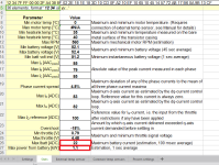
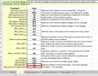
I went ahead and checked the stats in the latest S&S, and for the two sets you've posted images of, I get some fields with different results. I've pasted my own versions, with highlighted differences. Appears to be only the estimation fields for Max battery curent and Max power.

But between these and the negative torque (?) field issue, it makes me wonder what else might be happening. What if some of the fields for programming values are creating the wrong hex values to send to the controller? :shock:


12 34 7F FF 00 00 2F A4 38 8F 02 2E 18 1E 18 3D 10 CD 0F A2 10 EF 10 65 10 45 14 57 72 AB 17 B6 0A 9B 13 CF
gets me
View attachment 1

and
12 34 7F FF 00 00 32 96 3E 67 01 67 17 55 18 1D 29 6E 27 E4 2A 94 16 1F 2A FC 00 00 75 16 15 8B 15 D4 1D B7
gets me
 

Attachments

  • 12 34 7F FF 00 00 2F A4 38 8F 02 2E 18 1E 18 3D 10 CD 0F A2 10 EF 10 65 10 45 14 57 72 AB 17 B...png
    12 34 7F FF 00 00 2F A4 38 8F 02 2E 18 1E 18 3D 10 CD 0F A2 10 EF 10 65 10 45 14 57 72 AB 17 B...png
    27.4 KB · Views: 1,776
  • 12 34 7F FF 00 00 32 96 3E 67 01 67 17 55 18 1D 29 6E 27 E4 2A 94 16 1F 2A FC 00 00 75 16 15 8...png
    12 34 7F FF 00 00 32 96 3E 67 01 67 17 55 18 1D 29 6E 27 E4 2A 94 16 1F 2A FC 00 00 75 16 15 8...png
    27.5 KB · Views: 1,776
More details here:
https://endless-sphere.com/forums/viewtopic.php?f=2&t=67833&p=1450016#p1450016
but basically I fixed the wires with 8g, about a foot and a half on each phase. Still gets warm for the remaining few inches of 18g, but the 8g helps a bit to wick away the heat, without creating a lot more of it.

I also tried adding the estimated 10mohm to the motor resistance, and it caused a problem (fixed by restoring the old resistance value) where the motor would not run correctly at anything below several MPH. It would "catch" repeatedly as if it were ratcheting backward, trying to pull the trike against the direction I was going, on level ground. Didn't test this at hgiher speeds.

Tested ok offground, except that it kept getting "overcurrent" error (and shuts down until power cycled) if I pushed the throttle up too quickly. This doesn't happen when the wheel is loaded, on ground.

Also, occasionally, a tiny amount of throttle spins the wheel slowly *backward* instead of forward...only offground. Can't find a pattern to when it happens. Letting off and reengaging works normally.

Onground, it operates smoothly as before, as long as I'm on level ground. If I'm going up the driveway, and I'm stopped at the bottom of it, then it chugs trying to start going up the shallow slope, unless I use the other motor to help push it, but unless it's going a couple MPH or more it wont' run smoothly on it's own up that slope.
 
I've been pondering how to implement "features" in the SFOC that would otherwise require hardware changes, like reverse, or braking.

The latter is probably covered mostly by the eventual ability to setup negative torque when rolling back throttle, but if one wants to coast that wont' work.

There's a couple ways around that.

The first is to set it up so if you just let the throttle snap back to zero, it ceases positive torque, but doesn't apply negative torque. Then, if throttle is resumed, it works normally. Positive torque if throttle "demand" is above present "need", negative torque if it throttle demand dips below present need. But if throttle resumption demand is below present need, it does not do anything (no negative or positive), *until* need drops below present demand or demand is raised above present need, in which case positive torque is applied, until again demand drops below need and negative torque is applied.

The "throttle off with no negative torque" roll-off time would be configurable, at least within a small range, so it could be adjusted for various users' reaction times and systems. If it's set to zero, the function is disabled, and it applies negative torque at any time demand is below need.

This would be intuitive and useful, though I don't know how hard it is to rewrite the firmware to do it.


A second way would be kinda like the Phaserunner and a few other controllers have done it. A "brake zone" at the bottom of throttle output range is created, below what the typical (hall) throttle voltage would be, so below about 0.8v or so. This'd be adjustable like the regular throttle range is, and could be setup for any portion of the bottom of the throttle range, starting from zero for it's lower limit, and anything up to at least half of the throttle voltage range for it's max. This would control the negative torque.

The rest of the throttle range would be set for positive torque.

Throttles (like those on the vectrix) exist that have a "zero" detent and springreturn position right in the center, and rolling one way inceases the voltaee from halfway between supply and gorund up toward supply +. Rolling the other way decreases from halfway down toward ground.

A relatively simple circuit can also be made by a user to combine two analog voltage sources, like a regular throtle and a brake lever that outputs an analog voltage (though that itself might have to be built; I don't know of any presently for sale). The throttle would output in the upper part of the range, and the lever the lower part.

There are also other ways to generate the voltages needed to do this, but the point is that it can be done, so no new hardwae is needed in the SFOC, just the option to have two sections of the throttle input setup, one for positive and one for negative torque. WHen the negative torque field of ths option is set to zero, it's disabled and the SFOC uses the whole range of the input for positive torque (or at least, whatever the user has set the positive torque field is set for.


Adding a reverse function could be done in a similar way to the second method above, with a third segment of the range at the very bottom. This would e a bit more difficult to make intuitive, but if it was set so that it only works if one is at a cmplete stop, and then while the input votage required is held, it begins reversing the motor at a specific (user-settable) power (to make it controllable it probably should be kept low). I suppose the field could be made a range instead of just on or off at the bottom, but that would use up possibly significant input resolution for a little-used function.
 
Details over here:
https://endless-sphere.com/forums/viewtopic.php?f=2&t=67833&p=1450105#p1450105
but it looks like the remaining amount of 18g phase wres may not be getting too hot, at least at the 100A phase setting, with the average usage of a commute-like ride.

Temperatures inside the phase wire bundle sheath did not exceed about 50C, around 122F, in ambient temps of around 70F. That doesn't measure inside the axle itself, so it could be hotter in there where there's no airflow past them, and the steel doesn't conduct heat away quickly, plus the thick sheath / jacket is insulating too.

I don't really want to, but I should probably take the wheel off the trike, open up the cover, and examine the wires inside the sheath.
 
it'll be a pretty kickass controller, from what I have seen so far, for just about anyone

I am currently commuting on the SFOC5 again. Must say it's kickass even at this stage :D

-Super small for the power
-Great modulation except for the 0 rpm startup.
- fit and forget type of thing
- seems waterproof, it's currently in the salt spray from the front wheel since a few months of everyday riding without a single hickup.

Killed two kellys (silicon sealed), one adaptto (IP65) and some infinions this way..
Thumbs up!
 
I agree on all that...just that there are things that can be improved (the way it has to be setup, for instance) to make it more accessible to the average individual DIY ebike builder.


More test results from today:

I did around 9 miles of test riding, first 3 in the neighborhood as noted above, then another 6 on a trip to the store and back.

Mostly, things worked really well, and there was no overheating. (I converted an old BBQ thermometer to read that 10K NTC probe directly as F on the handlebars, so I coul see it at the same time as the motor temp on the CA screen). Max motor temp was around 50C, max wire temp was 125F for a short peak, mostly it was below 100F, ambient temps of 75-80F.

But around a dozen times (lost count), I got the "washboarding" effect, where it felt like the motor's phase field was out of sync with the rotor in a way that gives the sensation of riding over a series of ridges; it applies drag to the motor and pulls the trike to the right and slows it down. It would probably have just kept doing it if I didn't immediately let off throttle.

To make sure it wasn't some interaction with the CA's PAS control (which automatically pushes me up to 20MPH and then varies the throttle to hold me there), I switched that off and used only the throttle for the last half of the ride there, and the whole ride home. Still did it exactly the same way.

I cant' get it to happen consistently, but I had it happen more often under conditions that slowed the right wheel while throttling, like making a right turn, going up driveways or other slopes, as if this was causing the SFOC to lose track of where the rotor was in relation to the field.

It happened just cruising under power too, straight line. With traffic it was difficult to watch all the data at once, so I'm not totally certain of the speeds each time. Most of the time it would happen somewhere between 15 and 20MPH, the few times I actaully saw the speed at the moment it happend it was 16.something MPH or 12.something MPH or 17.something MPH. When it happened I'd lose a couple MPH almost instantly. The rest of the time I only saw the speed after it started and had already begun to slow me down, and those were all under 18MPH but over 15.

If I wasn't afraid of mechanically breaking something, I'd just let it continue to see if it recovered, but it's a pretty powerful problem, and I'm afraid it could break the axle again, since it feels almost as if it is slamming directions back and forth (I don't think it is, but I can't tell).


When it happens, I (think every time, but couldn't look or see to look every time) get the Overcurrent error (six on the LED panel), and sometimes the controller stops responding to throttle until I've come to a stop at the next traffic control, but most of the time it keeps working. Once I had to stay stopped a moment and reset it via the LED panel switch. When I did this, it reported error 1, that throttle was active at power up, but it was not. (don't have a voltmeter attached to read that continuously, but it wasn't being touched, and without the CA throttle output the hardware throttle output would definitely be well below what the SFOC is set for it's input threshold.
 
I do wonder what it is that keeps it from pushing more current at lower speeds. It's not BEMF, cuz that doesn't really start happening until the motor is spinning at some significant speed. Is it just the design of the SFOC5 itself? It's protections to prevent controller / motor destruction, limiting current until enough of a BEMF waveform is present to be certain of motor position/speed?
There is always a direct connection between the throttle and current output, no limitations. Position estimation is dependent on bemf, and will improve with speed. At lower speed the phase between rotor magnet field and stator induced field may therefore not be optimal, thus affecting torque output. Less bang for the buck.

I went ahead and checked the stats in the latest S&S, and for the two sets you've posted images of, I get some fields with different results.
Go down a little bit and check row 52. What does is say?
In any cell in the Stats sheet, put "=Settings!B89" and then in another cell "=Settings!B90". What do they return?

When it happens [washboard], I (think every time, but couldn't look or see to look every time) get the Overcurrent error (six on the LED panel)
Steady/Alternating 6 is "Motor temp sensor open or short circuit". Try disconnecting the sensor and see what happens. (Rapid blinking 6 with power cycling requirement is "Overcurrent".)
 
incememed said:
There is always a direct connection between the throttle and current output, no limitations. Position estimation is dependent on bemf, and will improve with speed. At lower speed the phase between rotor magnet field and stator induced field may therefore not be optimal, thus affecting torque output. Less bang for the buck.
That sounds familiar...you've probably explained this to me before. :oops: Sometimes I get braindead. :/


Go down a little bit and check row 52. What does is say?
On the main (settings) tab, there is no row 52; it goes from row 40 to row 423. :?

On the Stats tab, row 52 has a number of things, starting with Max Ibatt (ADC), then other stuff in various columns.

On the External Temp Sensor tab, row 52 has 110 and 680 in the first two columns.

On the Common Temp Sensor tab row 52 is blank.

On the Proven Settings tab, row 52 is blank.


In any cell in the Stats sheet, put "=Settings!B89" and then in another cell "=Settings!B90". What do they return?
I picked a cell at random by pointing at the screen with my eyes closed, and started there. In an empty cell (E34) I put the first one and get 58.1. I put the second in F34 and get 646.

Attempting to put either into G34 or H34 gets an error that "You cannot modify the read-only cells on a protected worksheet", and it changes the cell from empty to 0.

Putting the second value into cell E33 gets the word"e-RPM". E32 gets teh above error and 0. E31 gets the above error and "A". E30 gets the above error and "V".

More random cells with the second value: B19 gets 646. G17 gets 646. F19 gets "This command cannot be used on a protected worksheet". G11 gets 646.


Steady/Alternating 6 is "Motor temp sensor open or short circuit". Try disconnecting the sensor and see what happens. (Rapid blinking 6 with power cycling requirement is "Overcurrent".)
I don't have the sensor wired to the SFOC (it's monitored by the CA mostly so I can see it's value live on screen while riding, and secondarily so there's no way an insulation failure could kill the SFOC again, just in case).

I also don't have the sensor enabled in the settings sheet (no x in the box for that).

Also, while riding and even at the roadside with traffic whizzing by me, my attention is divided too many ways, and I can't always see the difference between a rapid blink and an alternating/slowblinking LED code. I think its' a time thing; it's probably just me and my wierd brain.
 
Some bad and wierd news; the phase wired melted, but not while in use, just while sitting there overnight powered on.


Last night, after I got back from the grocery/test run, the motor and wire temperatures both cooled down to ambient (low 70s F) while I unloaded the groceries and made dinner. Probably about an hour or so. The system was still powered on but not doing anything, just sitting by the back porch. I also examined the jacket and the phase wires that ocme out of it (or at least, the heatshrink over each wire I'd installed between the jacket and the splices to the 8g stuff). There was no damage or sign of heating.

At the time I checked the temperatures, I hand-rolled (walked) the trike over to the shed and inside it, so I could charge it up. The trike rolled easily like normal. No throttle or motor usage to move it.

Plugged in the charger cords for lights and traction batteries, verified charging in progress, and no LEDs lit on the SFOC Status LED panel. Note that I did not switch the SFOC off at the LED Status panel switch, and it was left powered with the rest of the trike during charging.

Pushed the trike a bit further in the door to get past it to leave the shed and go back to the house, still rolled easily.

Went out this morning to go to work, unplugged the chargers, and tried to roll the trike backwards out of the shed, but it was VERY difficult. I jacked up the trike's right side, and almost could not hand spin the wheel--it was pretty much just like the other day when the phase wires melted together during the test ride. I turned off the main power, and there was no difference. Disconnected the phase wires from the SFOC, no difference.

I did not look at the LED status panel before powering the system off, so I don't know if there was an error code or not. :( I also did not check the temperature readings; I wish I had, cuz it would've potentially confirmed or denied my theory further down this post.

Examined the phase wires near the axle, where they are only 18g, and could see the jacket is melted along the line of at least one of the wires. I cut the wires as close to the dropout/axle as I could, without removing the motor, and the motor then spun freely.

At that point, I had to get to work immediately, so I left the SFOC phases disconnected, and siwtched it off ath the status LED panel, powered the trike on, and went to work using just the leftside motor system.

ONce I got home from work, I had a chance to do an isolation test (passed 5.5gigohm axle to phases) examine the phase wires I'd cut off, and open the motor and check it out inside, and get some pics, which are over here to keep this thread less clogged up.
https://endless-sphere.com/forums/viewtopic.php?f=2&t=67833&p=1450462#p1450462

During the disassembly, I was very slow and careful, so I could see if there mgith be an origin point, but there doesn't appear to be.

Along the axle itself, the jacket and teh wires are undamaged, so the axle (and the metal tube/sleeve/dropout-spacer around it and the wires there) must've wicked away the heat enough to prevent a problem.

The blue phase wire is the least damaged of them all (and it was the only one that had any short to the stator before I fixed that, so that is highly unlikely to be a cause), and has no direct damage once it is inside the motor past the axle.

The yellow and green wires look in one place as if their insulation melted together and allowed them to short. This is outside the motor, in the seciton of wire I cut off before heading to work. Other places on those wires inside the motor look pretty bad, but they definitely weren't shorting, or the motor would not have turned easily. If they were *almost* shorting then I would've expected arcing across them while riding from the BEMF generated inside the motor, which would've applied braking on that side, but that did not happen anywhere during my ~5 mile commute. (~2.5miles each way).

There's no point at which insulation failed enough to short to the stator, either.


So...the wierd part...the damage was not caused by operating the motor. The damage had to be caused by the trike just sitting there, powered on, not moving, overnight, in a cold shed.

The thought crosses my mind that the SFOC5's "sleep mode" "holds" teh wheel in position somewhat, and this must use some current flow between phases (even if it is small, and doesn't use much battery current). This current shouldn't be enough to heat the wires, however, unless it's a lot more than I would've expected. Alternately, if it didnt' go to sleep for whatever reason, perhaps it is the small (tiny?) position sensing currents.

But if it *is* enough to heat 18g wire over several hours (with no windflow past them to cool them off), it would explain the wire damage.

Since it was sitting out in the nice cool breeze for the hour after I got home but before I put it in the shed, the airflow would've continued to dissipate the heat. But in the closed shed there'd be no breeze, so even though the ambient temperature would still drop, there'd be no sgnificant airflow past teh wires so in their insulating jacket they'd continue to warm up.


It couldn't be caused by a short inside the motor itself...as it wasnt' shorted inside the motor, just outside the axle.

However, there was still melted insulation inside the motor (which could, of course, have been caused during any of the testing the last couple days, and I wouldn't know, not having opened it until now), as well as outside the motor (which was not visibly damaged prior to parking it for the night to charge).

These appear to point to heating during the night, and I can't imagine anything in the system that could cause it, unless the SFOC's sleep mode (or position sensing) does keep putting a current thru it.

Even if the short itself already existed somehow, the wires external to the axle were not damaged in the way I found them in the morning. *something* had to pass enough current thru them overnight to cause the heating that damaged them...and I'll need to figure out what that is so it doesn't do it the next time I leave the SFOC powered on but the trike not in use (like during charging); it's almost certainly going to happen at some point, unless I build a relay system that shuts the SFOC off whenever the charger is plugged in--which should be totally overkill and unnecessary. ;)


It'll require dedicated testing to see if this could be the cause; if there is any significant current or heating, but first I have to replace the phase wires in the motor again, and instrument it for thermal sensing on the wires themselves in multiple places if I can. :/
 
Reminds me of what someone said about his Alfa Romeo, it would literally break down over night by just sitting. :)

Ampacity of 18g is 10-16 A, which is then derated for higher ambient temperatures or bundling.

At present, there is no sleep mode function implemented in the SFOC5, it will constantly switch a small current (the hissing sound). A sleep mode activated by some period of inactivity could of course be implemented.

(It is a possibility the washboard effect may stem from phase wires being borderline to insulation breakdown. Letting off throttle would lower the voltage to below breakdown. Vibration would then also be a factor.)

About the Overcurrent rapid blinking signal - Overcurrent will shut down the power stage and blink until restart, so not an ephemeral signal.

The LED-panel should never be silent, there should constantly be a battery voltage level indication on the LED-panel. However, this setting is given as a percentage (cell B29 in Settings sheet), so I can see how this may have gone wrong in a non MS software. I will eliminate all percentages from the S&S.

In relation to the stats you displayed earlier, in the Stats sheet pls take a snapshot of row 52 columns A-G.

When External temp sensor is de-selected, pls confirm settings 11-12 are zero, and when selected they are non-zero.
settings.jpg

I've had the same washboard effect (only slightly) but i think that time was overtemp in controller or motor, can't remember which.
With your current setup, likely motor temp. Winding temp is then >130 C, which may cause resistance temperature compensation function to overcompensate. It's a new functionality I will have to refine, great feedback.
 
incememed said:
Ampacity of 18g is 10-16 A, which is then derated for higher ambient temperatures or bundling.
As an aside, I wonder why this gauge of wire was used in hubmotor I took it out of? (IIRC, the Crystalyte X5304). I didn't use anything super powered on that motor, but I did use the same sensorless generic 15fet on it that is presently being used on the left side MXUS 4504 (althoguh it's been shuntmodded since then). It ddnt damage the wires then....though it was never putting 100A phse thru it. :lol:


At present, there is no sleep mode function implemented in the SFOC5, it will constantly switch a small current (the hissing sound). A sleep mode activated by some period of inactivity could of course be implemented.
There was one at one time, although a quick search found a post by me that said this seemed to have been gone in September 2018. :? I'm too tired right now to remember what I've seen in the last few days vs what I saw back then...I need my *own* sleep mode to engage. ;)

But it doesn't really matter which mode it was in at the time the insulation melted--it still happened while the motor was not in use, but system was powered on and switched on at the status panel. So *something* caused currents to flow, enough to build up enoguh heat to melt that insulation outside the motor.

(probably also inside the motor, but since I don't know what that looked like before the problem, it could've been cooked inside from previous tests; no way to know).


(It is a possibility the washboard effect may stem from phase wires being borderline to insulation breakdown. Letting off throttle would lower the voltage to below breakdown. Vibration would then also be a factor.)
I suppose so, but it passed testing at 250v on the isolation tester, from phase to phase (with the WYE point disconnected) and from each phase to stator. Then it repassed the axle/stator to phase test with the WYE point connected, at every stage of reassembly, and after that too (and even after the wire insulation melted today, once the short external to the motor was removed). I can test at higher voltages, the 500v and 1000v settings, but I don't know what the breakdown voltage of the winding insulation is supposed to be, and I'd rather not fry the motor if it's not actually done for already).


About the Overcurrent rapid blinking signal - Overcurrent will shut down the power stage and blink until restart, so not an ephemeral signal.
I probably saw things wrong on the panel, then, with everything going on while riding in traffic. :( I wish I could write the dashboard software so I could see all this stuff "live" (and record it in a human readable way, or at least to record it all as the realitme hex dump and then convert that to a human readable file); I just don't know enough about programming to do it myself yet, and just haven't had (and probably won't have in the foreseeable future) enough time (when I have energy at the same time) to figure it all out on my own.


The LED-panel should never be silent, there should constantly be a battery voltage level indication on the LED-panel. However, this setting is given as a percentage (cell B29 in Settings sheet), so I can see how this may have gone wrong in a non MS software. I will eliminate all percentages from the S&S.
That's different from the wayI understood it to work from the manual and stat sheet: the battery codes on the LEDs only start lighting up at a settable level (default of 50%), with code 15. Then 14 lights up at the next set level, and so on. (I've just left them at the defaults in all the recent testing; I don't recall changing them in previous testing either).

From the manual:
5.1 Battery voltage level gauge
Binary signals 15, 14, 12 and 8 are reserved for
indication of battery voltage level. Levels are
configurable.
Voltage is less than 50% of
full range
On-On-On-On
Voltage is less than 25% of
full range
On-On-On-Off
Voltage is less than 12.5%
of full range
On-On-Off-Off
Voltage is less than 6.25%
of full range
On-Off-Off-Off


From the stat sheet:
Battery voltage gauge
Display leftmost... ... when 30 sec average batt voltage is above xx% of full range. Corresponding cell voltage / pack voltage "Full range =
Fully charged voltage - Cut-off voltage"
4/4 status LEDs OOOO 50.0% 3.78 / 52.9
3/4 status LEDs OOOX 37.5% 3.68 / 51.5
2/4 status LEDs OOXX 25.0% 3.59 / 50.2
1/4 status LEDs OXXX 12.5% 3.49 / 48.9


I can see how they could be used to make a full-time battery gauge, so taht it's 100% SOC for code 15, 75% for 14, 50% for 12, and 25% for 8, but I don't recall ti being set taht way or described that way before. :?

In relation to the stats you displayed earlier, in the Stats sheet pls take a snapshot of row 52 columns A-G.
Sure; it's attached:


When External temp sensor is de-selected, pls confirm settings 11-12 are zero, and when selected they are non-zero.
Confirmed:
de-selected (no x in field)
0x18 0xCB 0xFF 0x1C 0x00 0x02 0x28 0xEC 0x00 0x01 0x00 0x00 0x02 0x20 0xFF 0xFC 0x00 0x00 0x00 0x00 0xFA 0xD7 0x00 0x00 0x00 0x00 0x01 0x85 0x06 0x66 0x00 0x00 0xF0 0x0F

selected (x in field)
0x18 0xCB 0xFF 0x1C 0x00 0x02 0x28 0xEC 0x00 0x2C 0x78 0x4C 0x02 0x20 0xFF 0xFC 0x00 0x00 0x00 0x00 0x02 0xA9 0x00 0x00 0x00 0x00 0x01 0x4F 0x06 0x66 0x00 0x00 0xF0 0x0F
 
Back
Top