Hall Sensors'b'Gone

I'm going to do what I can to reinsulate the damaged winding areas more permanently, with one or another type of insulating varnish, and redo the phase wires with the magnet wire, doulbe insulated with kapton tape (most likely).

I started a thread here:
https://endless-sphere.com/forums/viewtopic.php?f=30&t=99084
to find out what the best option(s) might be for this; there's links to various products (not all of which I can afford) I found here on ES and in searches elsewhere, for those that have done this sort of thing to compare and hpefully let me know which one(s) would be best to use.
 
That's different from the wayI understood it to work from the manual and stat sheet: the battery codes on the LEDs only start lighting up at a settable level (default of 50%), with code 15. Then 14 lights up at the next set level, and so on. (I've just left them at the defaults in all the recent testing; I don't recall changing them in previous testing either).
You are correct, functionality is as described in the manual. The latest S&S has it wrong, will be updated. At some point, maybe you can change the default just to confirm your excel software treats the entered percentage correctly.


Sure; it's attached:
Thanks. The discrepancy in "Max I_batt" and "Max power from battery" that you discovered above is because another bike voltage was entered in the Settings page on my side. Changed in the S&S so that this mistake is no longer possible to make, voltage is fetched locally in the Stats sheet.

It's true there was a sleep function before, when hissing sound was a nuisance. (As I understand it is now acceptable). A new sleep will be implemented.
 
incememed said:
You are correct, functionality is as described in the manual. The latest S&S has it wrong, will be updated. At some point, maybe you can change the default just to confirm your excel software treats the entered percentage correctly.
Sure; that's something I can try even while the motor is not connected to the SFOC5 (until I can do the phase wire and winding repair, which will hopefully be in the next few days). (Assuming the LED status lights will still show battery status regardless of other errors, like anything that shows up for motor not connected, if it does that).

I"ll set it to 100%, 90%, 75%, and 50% just to see if the LED status lights correctly indicate that.

Regarding the spreadsheet software, I can see if Openoffice / etc are still around, and if they operate the spreadsheet correctly (where the one I am using now apparently does not).


Thanks. The discrepancy in "Max I_batt" and "Max power from battery" that you discovered above is because another bike voltage was entered in the Settings page on my side. Changed in the S&S so that this mistake is no longer possible to make, voltage is fetched locally in the Stats sheet.
Ok. I'll get the new sheet and set it up, as soon as you post it up. (presently I still just see the one from 3-5-2019)


It's true there was a sleep function before, when hissing sound was a nuisance. (As I understand it is now acceptable). A new sleep will be implemented.
Yes, what little noise there is these days is fine. :)

Is the "new sleep" to prevent any chance of current flow while stopped for long periods?

(so there is no chance of what happened to my tiny phase wires happening to anyone else, if like me they forget to shut off the controller at the status panel switch but leave power connected)

I still want to test to see what exactly occurs, how much current, etc, if I can, also in the next few days. If you have suggestions on particular tests I can do with a small 2channel oscilloscope (which might have a hallsensor type current probe, cant' remember), or various multimeters, etc., I'm up for trying them out.
 
If you enter a percentage and send me the RealTerm send string 2 that would be fine.

The sleep will shut down the power stage, so no switching.

At throttle off there is just scatter, no discernable current in any direction. A very sensitive probe could perhaps display this with some granularity.
 
incememed said:
If you enter a percentage and send me the RealTerm send string 2 that would be fine.
Ok. Here's the RT send string 2 for the above percentages:

0x1A 0xE6 0xFF 0x1C 0x00 0x02 0x28 0xEC 0x00 0x01 0x00 0x00 0x02 0x20 0xFF 0xFC 0x00 0x00 0x00 0x00 0xFA 0xD7 0x00 0x00 0x00 0x00 0x01 0x85 0x06 0x66 0x00 0x00 0xF0 0x0F

BTW, when I changed the 50% in the first field to 100%, it automatically changed the other fields to 75%, 50%, and 25%, and will not let me alter any of them (just the first field, cell B29). Similarly, if I change it to 10%, the others go to 7.5, 5, 2.5. 33% gets me 24.8, 16.5, 8.3 for the others.

If it matters, it also allows values greater than 100% in the first field. ;)


The sleep will shut down the power stage, so no switching.
Makes sense. Would wake upon any throttle input above the minimum threshold set as "zero" (cell B20)?


At throttle off there is just scatter, no discernable current in any direction. A very sensitive probe could perhaps display this with some granularity.
I don't really understand, given that:
--wheel still wiggles around minutely when offground, throttle off, LED panel switch on, might not take much curent but there would have to be *some* in order to cause motion.

--there had to be current flowing sufficient to cause heating of those wires (even as thin as they were, at 18g) to the melting point of the teflon insulation and the plastic (unknown type) jacket around them, while the trike was sitting inactive but powered on overnight. I don't know how much current it would take to cause enough heating to do that....
 
BTW, I pulled out the old welder transformer, and it has 10g magnet wire on one side, and 14g on the other side.
https://www.endless-sphere.com/forums/viewtopic.php?f=2&t=67833&p=1451436#p1451436
file.php


Have to see what I can do with the dremel to make channels in the bearing ID, and possibly expanding the channels I started in the axle flats, to see if I can get 3x 10g wires in there, wrapped in kapton tape, with kapton also on the bearing and axle channels.

Tape might be here later today.

"CoronaDope" should be here tonight or tomorrow morning, and then I can try coating the windings with that, in the areas where I had to push them up away from the stator to remove the isolation fault.

(I also have the red insulating stuff on the way, if the CoronaDope doesn't do it, and the red stuff can still flow down in there).

I also have some fabric/teflon tape on the way, too, which may be able to be inserted under the windings, between them and the stator edges the problem is probably involved with. (and this tape can also be used as another insulation layer between phase wires and axle, bearing, etc).
 
THe repair is "complete" and appears to be working correctly, passes isolation test at 250v and 500v axle to phases.

Works on a quick test ride around the block on the SFOC5 , using the same settings as previously. PHase wires stayed cold (but it's also around 45F out there) to touch after ride, have to instrument the wires and see what they get to (outside the axle). Windings didn't get over 35C and cooled quickly to 25C.

We'll see how ti works on my commut tomorrow, and if it's fine and not hot phase wires/etc, I'll up the phase current to 150A from 100A.

I noticed an updated S&S file on the public folder this afternoon, so I grabbed that. Havne't looked at it; it has the same date as before, but an updated timestamp, on the public folder.


Pics and stuff over here:

https://endless-sphere.com/forums/viewtopic.php?f=2&t=67833&p=1451710#p1451710

https://endless-sphere.com/forums/viewtopic.php?f=2&t=67833&p=1451710#p1451708

https://endless-sphere.com/forums/viewtopic.php?f=2&t=67833&p=1451710#p1451702
 
Way to go, good to see you up and running so quickly.

The settings come out right from your change of battery voltage gauge percentage setting, so that's that.

About the torque up/down-ramp percentage settings in the Advanced parameters section, I downloaded Kingsoft WPS Office suite and opened the S&S, and there was no problem with the percentages (WPS Spreadsheets 10.2.0.7635). Then I did the same with Google Sheets, no difference. What I ended up doing was removing the '%' sign from the Format column, since typing '%' in a cell already formatted for percentages gives an error. (New S&S not published yet.)
 
incememed said:
Way to go, good to see you up and running so quickly.
Thanks...although something is still not right. I get error 10 (LEDs 1010) periodically during a ride, and I have to cycle the switch on the LED status panel to clear it. I haven't yet been able to determine what specific conditions cause the error, but I wonder if this is related to the error 6 I saw before the skinny phase wires melted.

I verified with the SFOC (phase wires) and CA (thermal sensor) disconnected that the isolation tester still passes all phases to the axle. Haven't opened it up to disconnect the WYE point and check for inter-phase isolation, but that probably is not necessary (and is a risk of causing other problems to open up the motor, disconnect and reconnect it and reassemble the motor).

Anyway, perhaps the motor parameters have changed due to the redoing of the phase wires? Shouldn't be that big a change, but I'll have to setup a testing rig for resistance testing, and now that i have the halls wired out I'll be able to verify the approximate kV.

Inductance I'll have to get a cheap tester for; I don't have anything that cna directly test that. I can look up how to determine inductance using an oscilloscope; I'm sure there's a way, maybe with an AC input of known frequency, and a known capacitance and see what the phase shift is?


FWIW, during the ride, the winding temperature never got above 26C (and probably not that high, becuase the position sensing in the phase wires induces noise in the thermal sensor wires). The phase wire thermal sensor is less reliable in exactly what it's sensing, because it's just ziptied to the outer jacket of two of the phase wires (the two that come out of the outboard axle), but it neer went above 76F. Ambient temperature was about the same. I might insert the probe under the jacket of one of the wires, after I wrap the tip in Kapton in case it scratches the wire coating, to get a more direct reading (without the airflow cooling the sensor


About the torque up/down-ramp percentage settings in the Advanced parameters section, I downloaded Kingsoft WPS Office suite and opened the S&S, and there was no problem with the percentages (WPS Spreadsheets 10.2.0.7635). Then I did the same with Google Sheets, no difference. What I ended up doing was removing the '%' sign from the Format column, since typing '%' in a cell already formatted for percentages gives an error. (New S&S not published yet.)

:oops: Ok, now I am embarrassed. I was not actually inputting the % sign....I didn't realise I was supposed to (somehow assumed it was numeric only). :oops:

0.05 *is* actually the same as 5%, so that's probalby why it would not accept anything higher.

I compared the RT send 1/2 fields, with each version of the value, and they both come out the same (0x06 0x66) for fields 29 and 30 of the second send field, so it doesn't require the % sign.

However...if it really is correctly reading the value and correctly making the right hex to send, then either I misunderstand what the torque down ramp is supposed to be doing, or it isn't doing it.

I *thought* the field was to set the negative torque applied when throttle demand is made less than that presently provided, to provide motor braking. But there is no noticeable negative torque regardless of how I use the throttle, it simply glides down if I let off the throttle to zero or even just almost zero.

So I looked up "negative torque" and found I misremembered:
https://endless-sphere.com/forums/viewtopic.php?f=2&t=30680&p=1394460&hilit=negative+torque#p1394460
incememed said:
Absolutely, the way regen would be implemented in vector control is negative torque demand (instead of just zero, as throttle off would normally render), which would be revoked as the vehicle approaches zero rpm. The torque magnitude would be a setting, the negative demand would kick in when the conditions Throttle off and Above a certain rpm are both true.

As of now, by increasing the Torque down-ramp setting, power can certainly be regenerated while slowing down the vehicle, at the expense of coasting.

I will have to do some testing without touching the ebrake lever (such an ingrained habit it'll be hard :oops: ) and see if there is any regen current coming from the SFOC for certain (AFAICR there hasn't been any). ( I have no way of disabling the generic leftside controller without literally cutting the power wires to it, or else opening it up and cutting (or installin a switch in) the "keyswitch/ignition" line that passes battery power to the LVPS for the brain section; neither of those is a likley thing to get done unless it is absolutely required).
 
More testing on my commute today, and then a little more on a side trip to the store on the way home.

If I turn the Cycle Analyst's speed limit down to 5mph (so it doesn't output any throttle above that speed), and use only the thumb throttle to control the SFOC/4503, then I can avoid the error 10 / shutdown, by not using full throttle when I am at higher speeds than around 15ish MPH.

It appears that if I keep pushing full throttle, first it gets juddery, then almost immediately afterward it gets error 10.

If I pull back on throttle as the first judder, it doesn't get error 10 and I can continue using it.


THe way the CA is setup right now for PAS, is that as longa s I am pedalling at my normal rate, *and* the trike hasn't reached the speed limit of the current preset (5, 10, or 20MPH), then it keeps pushing full throttle until it does reach the limit, and then it drops throttle off until the trike holds that speed, and then it holds throttle there.

I think the problem I'm having with it is when using the 20MPH preset, is that holding of full throttle as it gets up towards 15-20MPH region. Since it doesn't have any feedback from the controller that there is a problem, it keeps trying, utnilt he controller decides it's had enough adn shutsdown wiht error 10. I can instantly shut off the CA's output by pedalling backwards just a bit, but it takes me more time to get my legs to do that than it does to make my thumb let go, and apparently ti's enough more time that I can't stop it from occuring via pedals.

So until I can do the testing to verify the motor's present characteristics, I'll just not use the CA to control the SFOC above 10MPH, and it should be ok. Avbove that I'll just use the throttle to do so. I still need to setup the CA to have fine control over the throttle with the pedals, but it's kind of complicated, so I haven't gotten around to it.
 
I disconnected the CA's throttle output, so only the hand throttle is runing the SFOC. Easier to control exactly what power it makes then, but it does still get the judder, and the shutdown (and once an overcurrent, when the below happened) error code, if I do push throttle too far up while above around 15MPh or so. (can't tell exactly since I'm in traffic, not enough attention to go around).


HOwever...testing further may be delayed a bit; the outboard axle broke AGAIN, though not where I welded the new piece on, instead it was a few millimeters farther inboard, right at the outboard edge of the bearing race. Turns out this is where the angled hole MXUS originally drilled thru the axle for the cable almost meets the sidewall of the axle, below my welds...and apparently just *barely* breached the side after I dremeled out the wire channels along the flats. I thought I had weld-filled that angled hole almost completely, but there was a huge void that I missed. Taht probably weakened the axle enough to cause the break point.

It broke in a right turn (I felt it) and when I straightned out and applied SFOC throttle, it immediately gave error 6 for overcurrent. Most likely that's becuase when the break happened, it *also* shoved the inboard end into the clamping dropout just enough to pinch the inboard phase wire between the flat face of teh dropout and the outer lip of the freewheel (and it also broke the weld on the top of the clamp...or that weld broke and allowed the movement that then broke the outboard axle...no way to know which went first). Anyway, the broken axle cut into the insulation of the phase wires on the outboard side, so it most likley made a fairly direct short between phases when the SFOC tried to put current thru them, alhtough it was not enough of a short to create more drag on that side than the tire rubbing on the frame and fender wall did.


I'm fixing the axle tonight (actually already welded it back, and am inside eating dinner and resting a bit since work wore me out before I even had this problem) but I don't know if I'll have time to ensure the phase wires are thoroughly insulated to be able to use it as a motor...but I HAVE to be able to use it as a *wheel*, no matter what. I don't have a spare one built up right now. :/

PIcs and details will be over in the SB Cruiser thread once I have time to do that, and I'll edit a link in here.
 
The repaired axle survived today's work commute. I might have time Wed or Thu to work on rewiring it again.

I think I have a workable idea for a complete axle replacement using a tube with a tube clamp, and larger ID bearings with same OD. Gonna put it in my trike thread once I sketch it up.
 
Axle repair has survived (without power) the normal commute abuse and a store trip with over 100lbs of groceries and stuff, for the past week or so.

Had to do long-delayed yardwork on that "weekend", so had no time to work on the trike. Am hoping to do the new rewiring this wed or thurs, if nothing else comes up. Then I can at least resume testing on this motor. Need to order a cheap LCR meter or something, to verify inductance on these motors, and setup a rig to test the other parameters, so I can test the SFOC properly with the 4504 on the left side, or even replace the 4503 itself with something esle, like the ex-Stromer motor, or the old X5304, etc.

I haven't drawn up the axle idea yet; if I'm lucky I'll have something worked out to post this week, and then see about getting the bearings needed to implement it, and making parts as I have time, including an axle press, to try to do the replacement itself (including the complete replacement of trike dropouts on at least one side to test the idea) during my next week off at the end of April.
 
I've been looking on Amazon (havent' got to ebay yet) for the best options in LCR meters, but I have yet to find one under $100 (which is still well out of my budget for that part of this project) that will do sub-100uH inductance testing, or low-milliohm resistance.

Lowest capability I found so far was this:
https://www.amazon.com/CAMWAY-Capacitance-Inductance-Resistance-Self-discharge/dp/B07DVJB865/ref=sr_1_7?keywords=LCR+tester&qid=1553823462&s=musical-instruments&sr=1-7-catcorr

Wide Measuring Range 200pF to 2000uF, Accuracy ±(2.5%+5),
200uH Tto 20H,Accuracy ±(2%+5),
200Ω to 200MΩ, Accuracy ±(0.8%+2)

which is nowhere near good enough. The others are worse; at best they'll do (depending on which vendor you believe, of the few that bother to state any specs) at inductance is about 20mH; I don't recall the resistance limit. Some only specify the upper limit, and don't mention the lower, so have to assume they can't reach as low as needed.

I'm still looking around...but if anyone can point me to one that will measure at least the inductance of typical ebike motors, and preferably the resistance, with some accuracy, I'd appreciate it. :)
 
A thought, that should've occured to me long ago, that would make this controller much more user-friendly for setup (since inductance and resistance of various motors are generally not documented anywhere):

Is there enough room in the firmware (and time/willingness on your part :) ) to add a feature? I don't know how much space it might take or how complex it is, but couldn't the controller itself do an inductance test, to find out the *actual* inductance of the motor? It's able to send signals of varying frequencies to the motor, and currents, and voltages, so couldn't it use that to determine inductance? (sorry I have no more idea than that of how it would do it, but it seems that it could?)

Similarly, couldn't it test for the resistance of windings and phase wires?

I think the controller will already know the voltage, and the current, applied to the phases, right? So it could use that to determine the resistance?

The cheapo LCR meters can do this sort of thing, so electronics as sophisticated as the SFOC5 ought to be able to as well, without any hardware changes?
 
I have used it together with a scope and external current sensors (the internal ones are too coarse) to do just that. It was ok for inductance, but not very reliable for resistance. Using series connected high accuracy resistors was much better for that.

However, most of the motors in the Proven settings tab were dialed in using manufacturer provided kv and searches on forums (I only recently acquired fancy meters). Of course, the more accurate the better, but for operation at low to medium currents the tolerance is quite wide.

Some systematic parameter variation across a couple of commutes should get you a functioning setup. If not, we need to assess the situation. A couple of posts up kv was estimated at 12, which may be a good candidate to fixate, and vary R and L.
 
Ok, I FINALLY got the motor wires readded *again* :oops: :lol: and verified isolation with the tester from phases to stator/axle/frame/etc.

But...the firmware update, or something, has gotten it "stuck". Hopefully I'm just stupid and can't see the obvious. So...here's the details on what I did:

Hooked up to the SFOC5 with the existing (previous) firmware, and verified operation as it previously had worked (offground, as trike is still on it's side, to enable me to see what's going on, and troubleshoot, if needed). Battery about half full, and the SFOC5 indicates this with the slowly repeating 4-lights (code 15) on the StatusLED display.

Powered the system off, and switched the StatusLED panel switch off. Hooked up the USB-serial cable to the laptop, setup Realterm to receive, and plugged in the serial of that to teh SFOC serial. Got the usual expected stats (didnt' save them as they'd jsut ahve normal data).

Disconnected serial, closed Realterm, and opened dsloadergui, set it up per the manual as usual, and loaded up teh newest firmware ambw20190415.hex. Dsloadergui verified it as ok, so I clicked the write button, and got the "wating for bootloader" message, plugged in the serial cable to the SFOC, and it displayed the usual writing and verifying stuff, finally coming out with this, showing worked fine:


Initiating write...
Searching for bl . . . . .
Found dsPIC30F4011 fw ver. 4.0.3
Waiting for the boot loader to be ready...ok
Parsing hexfile...
File timestamp: 4/16/2019 12:25:58 AM
Opening hexfile...ok
Validating hexfile...ok
Hex file successfully parsed
Writing flash....ok
Tx 22.9kB / Rx 234 bytes / 17s
Write successfully completed

Disconnected the serial, then powered on the system (didn't yet switch on the StatusLED panel), and it gave the startup-LED-sequence-count, where it lights the 1 LED, then turns that off and lights the 2 LED, then 4 LED, then 8 LED. That seemed strange, as I *thought* it only did that when I turn the StatusLED panel switch to On...but I can't remember for *sure* if that's how it normally works.

Anyway, it blanks for a second (or less) and then changes to a flashing code 9, faster than 1Hz, and doesnt' respond. I siwtched it on at the StatusLED panel, and nothing changed. It didn't give the startup LED sequence. :?

I powered the system off, switched off the statusLED siwthc, waited a few minutes, and powered it back on, and got the same thing again--startup sequence when switched off at panel, but no change when switched on.

I switchd the panel off again, and hooked up the serial, with REalterm on to receive, to see what the stats would be, and got just garbage. I tried a number of times, including with a different USB-seiral cable, and each of the lines below is the complete data recieved for the first four tries (I stopped saving the data after that, as it appears to be random):

00 01 00 00 42 00 08 00

FC 00 00 12 00 00 00 00 C0

2E 00 00 07 00

00 00 00 00 00 00 A0 FF FE


Closed Reatlterm and opened DSloadergui so I could check the bootloader at least. But when I try, I get this:
Searching for bl . . . . .
Found PIC24FJ256DA110 fw ver. 0.1.6
Wrong pic detected(255/FF)/selected(14/E), aborting
I tried several times, including power cycling everyting (even the laptop), different USB ports, different serial-USB, etc.

I even tried it with the cable to the StatusLED panel disconnected at the SFOC end, in case somehow something went wrong with the switch or cable or panel between when it worked with the previous FW and after updating to the new (unlikely as that would be), with no change in results.


I didn't expect it to work (and it didn't) but I also tried to use Raealterm to update the settings, since the only LED code I do get appears to be "low voltage cutoff", so I figured maybe the firmware came with settings in it that are expecting a minimum voltage higher than my pack's voltage at half charge. But it didnt' work (and there are no characters echoed from the SFOC).

I also shut everything off and charged up the batteyr to full (57.7v), with no change.

I haven't yet tried seriesing another battery with the regular one, to bring it up to say, 80v (near the max voltage the SFOC could handle), in case that is enough to fix it (the stat sheets come preset to 30s, and the LVC there is 102v, which is higher than this SFOC can even do).


So...any ideas?
 
Welcome back! What the LED-panel On/Off switch does is to connect the internal 12V/5V converter to the 5V network. This will fire up the processor and off we go with the LED-panel start sequence.

If the start-sequence is activated with the LED-panel On/Off switch in the Off position, it means 5V is being fed from somewhere else. This is the case e.g. when the programming cable is being connected, effectively feeding the the SFOC processor from the host computer.

The start sequence being activated with the LED-panel On/Off switch in the Off position and no programming cable connected indicates 5V is being back-fed via the throttle. This is fine, just make sure SFOC battery terminals are connected, otherwise it will sense 0 voltage and flash low voltage error.
 
If back-feeding (starting-up, triggering the LED startup sequence) through the 5V throttle supply, then make sure the LED-panel On/Off switch is in the On-position before doing so. This is a 12V switch that feeds the gate drivers and the battery voltage sensing unit.
 
No, it's not being fed by the throttle; I made sure of that when setting it all up. :)

Besides, it all worked perfectly fine until the moment the firmware update successfully completed. After that, :(

(and it's even with it connected to the battery system and powered on).

AFAICR it doesn't startup or give error unless it's powered by either the programming cable or the battery with status panel switch on, I don't remember saying that it did but maybe I typed something wrong.


So I guess I just missed the start sequence previously whenever doing data reads or other StatusLED panel switch off operations. :oops: Probably cuz I'm usually busy connecting the serial cable at the time, and not looking at anything but that adn the laptop screen.

However, the problem still stands: I get the flashing error 9 (1001), and nothing else on the panel.

Trying to talk to the bootloader via DSloadergui gets the error listed in the report, showing the wrong PIC.

Only garbage comes back to Realterm when connecting the serial port to read stats.

No response comes back to realterm when sending settings.


I'll retest everything again tomorrow (later today, really, it's already 230am), as I had to stop on that till hearing back, and was working on other bits (new fork and front wheel and brake, still not ready but getting there).

HOpefully I"m just being stupid and missing something, but I am pretty sure I covered it all. :/
 
The firmware was shipped with the facilities for programming Settings and receiving Stats disabled. My apologies.

I have put the previous firmware in the Public folder. To make the installation as fail safe as possible:
  • Disconnect everything; throttle, LED-panel, battery leads, temp sensor
  • From a rebooted computer, don't start RealTerm, only ds30
  • People have complained you needed to be too quick when connecting, I upped that time-out but it may need even further delay to be comfortable. But for now, be somewhat snappy...
 
That's good news...I went thru everything again (before checking and seeing this post) and this time I did get *slightly* different results, but still had the eror 9 (low voltage) regardless of power connection state, switch state, etc., and couldn't change settings or get stats (but DSloadergui could at least talk to the SFOC now and get the right PIC...steps were the same so I don't know what actually changed). I had even gone ahead and gotten Docklight to try in case my Realterm simply didn't work right anymore (which would be wierd, but not impossible).

Anyhow, I'll get the firmware from the public folder and see what happens. :)
 
Lost the detailed reply due to poor wifi connection. :(

Flashing to the old october 2018 fw on the public folder works, including using my existing settings for that firmware, and it operates as it did yesterday before attempting the new april 15 fw.

Since that worked, I tested using the april 13 fw you had emailed me that I didnt' get to try, and it flashes and gives stats, and echoes back the characters for sending settings (generated with the april 13 stat/sttings sheet), but it does not appear to accept them. Doesn't respond to throttle, and blinks the 50% battery remaining eror 15, even though the battery is fully charged and the SFOC does have the correct voltage at it's input (57.7v)

Reflashed back to oct18 fw and again it works correctly with my settings, etc.

So now it's basically operational, but only to the point we were at effectively months ago.

I would really like to try out the new april firmware as soon as you can post a version that will accept settings and provide stats, etc. :)
 
I did a test ride up and down the street, just a few hundred feet, to test other things on the trike (new front brake, fork, wheel), and used the non-SFOC motor/controller for almost all the power needs, and accelerations. I did try adding a bit of SFOC throttle, gently rolling on, a few times, but since it randomly "glitched" (stuttered) and then cutout with blinking error 12 (leftmost two LEDs), I stopped using it's throttle at all, until I would have time (not today) to troulbeshoot it. I've attached the settings file I used with the Oct2018 firmware, if it's helpful. I have not tried to get stats from it yet, due to the below.

When I got back to the house, I parked it in the yard and rolled it over on it's side again, to fix the wires on the Cycle Analyst to the thermal sensor in the motor (I hadn't reattached them after the latest repair), and the bakc of my hand brushed the surface of the SFOC, and it was so hot I jerked away and fell back in surprise. :shock: I then touched it wtih my fingertips, and could not keep them on there for more than a small portion of a second--whatever my reaction time is, that's how long.

Since there was no reason I'm aware of for it being so hot, as the motor itself was basically just at ambient -- I couldn't feel a difference in temperature on the phase wires, axle, covers, or rotor, from ambient, which my other sensor on the bars said was just 77F, I immediately disconnected the SFOC from batteyr power and motor phases, not knowing if the heat was going to increase or decrease at that piont, not knowing the cause of the heat.

Anyway, I then completed fixing the connectio for the CA sensor, which then read 27C on the CA screen. Basically ambient--close enough that the difference is about the same as the innacuracies of the sensors/etc.

I borrowed by brother's IR thermometer, and the case of the SFOC, now several minutes after disconnecting power/etc from it, still read 130F !!! I don't know how hot it was before, but it was enough to actually melt a tiny spot on the white plastic sleeve of a cable passing next to it that happened to be pressed against it's casing somewhere. It didn't damage the insulation on the actual wires, just the outer jacket was damaged (indicating the heat came from outside the cable, not from the cable itself, which carries no current, is just for the thermal sensor for the CA). I'm guessing that's over 150F to do that, without looking at the markings on the jacket that might say.

I'll know more later, perhaps tomorrow (but I go back to work; my vacation is now over), if I have time and energy.
 
Between work and home stuff and other problems with the trike (building a new fork that can handle the trike load among other things), haven't been able to get back to SFOC testing till today.

FWIW, I did test the 4503 motor itself with the generic 12fet "30a" trapezoidal sensorless controller, and it works fine with that, including what little regen that controller can do; been using it for a month that way now, without either the controller or the motor getting hot. Even if I use *only* that motor to accelerate/decelerate/cruise, leaving the other one's controller off, the motor only gets to 122F max on my commute, pushing it as hard as that little controller can manage, and that's on a 100F day, 100-105F was typical before the weather turned hot. The controller itself only gets a few degrees above ambient.

NOte that all testing below is with the trike on it's side, wheels off ground, no load.

Today, for the first time since the previous post, I connected the SFOC up to the laptop via usb-serial, left the LED Status/switch panel connected, with no other connections to anything, and got no stats back from it, but it did go thru the correct LED sequence for being connected, and had the switch off.
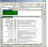
060519 stats check.png


So I disconnected it. Then, since the previous superheating problem occured on the 4503 rightside motor, I looked up the previous parameters for the 4504 leftside motor we'd found and/or calculated, and created a settings string in a fresh S&S sheet from the Oct18 version (since that's the FW presently in the SFOC).

4T:
kV = 8.9
inductance = (307 ?) uH
phase resistance = 0.110ohms

0xF0 0x0F 0x04 0x89 0x19 0xF9 0x00 0xB3 0x04 0x74 0xFF 0xF9 0x01 0xAD 0x00 0x96 0x17 0xA8 0x16 0xB0 0x1A 0x93 0x11 0xAE 0x75 0x30 0x05 0x90 0x1C 0x1F 0x03 0xF3 0x63 0xD6

0x19 0x1E 0xFE 0xDA 0x00 0x01 0x28 0xEC 0x00 0x01 0x00 0x00 0x00 0xD6 0xFF 0xFE 0x00 0x00 0x00 0x00 0xFA 0xD6 0x00 0x00 0x00 0x00 0x01 0xC2 0x06 0x66 0x05 0x64 0xF0 0x0F
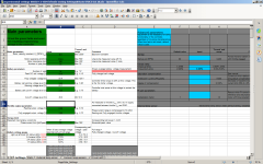
060519 simple offground spinup test 4504  settings sheet.png

The SFOC correctly echoed back the data, and when disconnected from serial and reconected, it correctly produced stats (though they are not all valid, that's ok, it confirms the MCU is alive).

12 34 7F FF 00 00 2A CB 72 9B 01 2F 1A 30 1A 55 24 32 24 66 23 02 E7 4C 23 01 00 00 6D 67 19 6F 03 EE 13 92

Then I disconnected serial, connected up throttle (the leftside one, so different from the previous test), power, and phase wires to the 4504 on the left side, and switched it on at the Status LED panel.

This powered on normally, no error codes, and began slightly wiggling the wheel as expected.

Very gradually gave a teensy bit of throttle, and it spun the wheel backward just an instant as I let go of throttle.

Powered system off at the battery cutoff, and swapped two phase wires. Powered back on.

Very gradually gave a teensy bit of throttle, and it spun the wheel forward slowly increasing in speed until it reached the no-load max for whatever current that is. Increased throttle slightly, and it spun forward until it reached whatever the max speed was, and further increasing throttle made no increase in speed (or any other behavior). This took about 10 seconds to do, total.

I let go of throttle, and motor spun down at normal coasting / freewheeling speed, didn't appear to be decelerated by the SFOC at all, even though I have the Torque Down Ramp set to 5% (the max). This is consistent with every other attempt to make TDR brake the wheel--it doesn't do anything. I wish it did, as sometimes require regen braking to slow sufficiently depending on road conditions and cargo loading.


Anyway, as soon as I let go of throttle, I looked at the temperature monitor for the sensor I'd pressed against the SFOC's case right next to the heatsink bolt head in the middle, and saw it rapidly climbing past 135F, reaching 140F in the time it took me to reach down and turn off the battery disconnect, and continue climbing.

I then turned off the LED status panel switch, and connected the SFOC serial to the laptop, and got these stats, indicating it's max temperature was 230F (min was 45F, which isn't right, as it was 100F outside, stable for hours, at the time I did all this testing).

The motor stayed at ambient, 100F. (thermal sensor read externally rather than by SFOC, so no possibility of shorts like that which caused the damage it had to be sent back to you for last year).

12 34 7F FF 00 00 3E 62 72 4A 01 E1 1A 5D 1A 7D 04 21 04 8C 06 62 FA B6 06 21 11 6A 76 41 1A 23 01 5F 09 E7
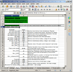
060519 simple offground spinup test 4504 stats.png

So, whatever is causing the SFOC to heat up so rapidly with almost zero use is not the 4503 motor itself, or any of the phase wiring associated with it. Since the heating also occured with the 4504 and a different throttle, it isn't either of those, most likely.

I am still waiting for the SFOC to drop to ambient again, and then I will test it with no motor attached at all, and no throttle, and see how fast it gets to what temperature.
 

Attachments

  • experimental settings 060519-1 4504 leftside testing Settings&Stats SFOC5 Oct 18.xls
    134.5 KB · Views: 27
  • Settings&Stats SFOC5 Oct 18.xls
    185.5 KB · Views: 27
  • ambwOct18.zip
    20.4 KB · Views: 27
Back
Top