unemployed.Bobcat said:
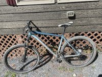
-My design will mount the hub motor in the middle of the triangle. Then the front brake rotor
on the hub motor will be replaced with a gear that runs a chain to the cranks. Two gears will be mounted on the cranks, one to the motor and one to the rear cassette.
Similar to the designs in this ES build:
https://endless-sphere.com/forums/viewtopic.php?f=6&t=38553
That's a thread about a lot of completely different designs, so you'll need to point to the specific post about the specific one you're referencing.
If it's about the very first one by Bzhwindtalker, then that one drives the rightside crank via a second chainring (whcih you don't have) inboard of the chainring that drives the rear wheel. AFAICT those two chainrings are both mounted on a freewheel (probably the white industries or ENO) that's on a "trials crank" that is threaded for a standard freewheel like that used on rear wheels. Thus, the cranks are not driven by the motor but the motor will drive the rear, and the cranks can also drive the rear.
I can't tell if there is a freewheel on the motor casing or not; if there is not the cranks do always drive the motor, if there is then they only drive the rear wheel.
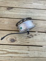
Regarding swapping out the brake rotor on the motor:
That's on the left side of the motor. If you put a sprocket there instead, the only way *this* kind of motor (geared freewheeling hub) can drive a chain with it is if your chain to the pedal chainrings is on the left side, too, like a Stokemonkey (which precludes a standard freewheeling crank). It does, however, make it easier for you to add teh sprocket to the cranks--just change the left crank for a right crank with chainwheel on it.
")
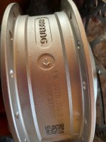
If you flip the motor so the rotor mount is on the right side where the normal chainwheels are, the freewheel inside the motor (often called a clutch) prevents the motor from driving the casing and thus the rotor/sprocket. YOu *can* open the motor and lock the clutch (welding, etc) so it can drive the casing either way, if necessary.
And not that it matters much, but this may make it easier to get things across, if you think about terminology before using it
I realize it's fairly pedantic to say at this point (you may find I'm like that :lol: ), but I'm just putting this out there to see if it steers how you think about things down a more detailed path (which you'll need when doing and documenting this project). The motor itself doesn't have a front (or rear) brake rotor, because it's just one motor for one wheel that is not going to be in the front or the rear but in the middle.
Yes, it is usually used *as* a front motor, so technically in that usage it would be the front rotor...but the motor itself can also be used on the rear. (albeit, without a pedal chain to it in the normal way; but it can be done and even have a DIY freewheel added). If it matters, I edit a post sometimes dozens of times before it's "posted", trying not to leave anything unclear. (not that I'm perfect at that, either

) (I've also *never* been accused of overthinking anything.
-thanks for your comments about freewheel BB. I didn't even know such a concept existed. I think I am leaning towards staying away from it because of the complexity you mentioned. I stated that throttle control was out because of the direct link between the motor and the cranks, which would cause throttle to apply odd pressure to the pedals, although maybe I am overstating the affect.
The throttle will only apply the pressure you choose, and you have complete variable control over that in realtime, so you can vary it to match your cadence, etc.
Any PAS control you have will almost certainly have a significant response lag between your pedalling input change (cadence and/or torque) and the motor system's change in operation. Most systems need to use both torque and cadence to do the controlling, and to detect cadence it takes time to count magnets passing a sensor and realize the speed changed...the more magnets the less lag, but it's always still there to some degree.
Now...here's a catch: If you do NOT have freewheeling cranks (where the magnet that drives the PAS sensor is actually on the cranks, not the chainrings driven by the motor), you probably shouldn't use cadence-based PAS, because the motor will keep driving the cranks (and thus the cadence sensor) even without your feet on them, so it will NEVER STOP.
(Not completely true; you *can* stop it using hte ebrake input, which then, once the motor stops the cranks, will be "reset" to no input and wont' self-drive again until you pedal again...but it wont' stop *by itself* when you stop pedalling, and that could cause a loss of control and a crash/etc if it ever surprises you for any reason).
Torque based PAS *might* work more safely, as long as the sensor you use is detecting the difference in tension across the cranks and the motor drives the right side with the pedal chain, or the sensor is detecting the actual pedal / crank pressure/tension.
But a throttle is probably your best simple and certain option to control a non-freewheeling-cranks system.
-I am intrigued and slightly confused by your comments reguarding full power PAS...seeming to indicate there are only gross steps when it comes to most PAS systems?
That's somewhat correct. Let's take an imaginary typical common multilevel cadence-detection-PAS controlled system with a handlebar display, where the levels are different speeds (some use different watts instead). I'll use arbitrarily simple numbers for everything; a real system might be divided up differently.
It has 5 levels of PAS, plus a 0 level that disables it, and it turns on at that 0 level so you can't accidentally make it take off while mounting hte bike.
To use it, you press an up arrow on the display, and it changes to the first level; that has a 5mph speed limit, so as soon as you start pedalling (well, as soon as it detects you pedalling) then it will apply whatever power is needed to make the motor spin at the speed that makes the wheelspeed sensor read 5MPH.
To go faster you press the up arrow again, and it goes to level 2, which has a 10mph speed limit, which it will maintain by auto applying whatever power is needed to do that.
And so on up to level 5, which has a 25mph speed limit.
When you stop pedalling, it stops applying motor power.
If you want to go some other speed than one of those five speeds, controled only with the PAS, you have to pedal, stop pedaling, pedal, stop pedalling, over and over, so that it will burst up in speed and then coast down, over and over. There's no fine control wtih the PAS.
Now, many of those systems have throttles, too, so you can set the PAS to either a level below the speed you want to maintain and then use the throttle to hold the speed, or turn off the PAS by setting it to level 0 (which usually leaves the throttle working).
Most of these have significant delays between start/stop of pedalling and start/stop of motor, when solely controlled by the PAS cadence sensor.
I like the sound of using a dumb controller combined with cycle analyst V3... I would like to hear more about that.
The best source of info is the https://ebikes.ca/product-info/grin-products/cycle-analyst-3.html page. There's written documentation, picutres, and videos.
But basically, the CAv3 is a computer that takes in various sensor input (ebrake lever switch, throttle, wheelspeed sensor (whcih can be used for motor RPM instead), thermal sensor, battery current sensor, battery voltage sensor, PAS cadence and torque sensors, etc) and then outputs a throttle signal based on your chosen settings and limits. It also monitors battery usage and capacity, etc., and other statistics.
Now, the CAv3 can use several different PAS (and throttle) modes, and even different sensor types for PAS.
If you use cadence control (simple, cheap, it's what I'm still using on SB Cruiser), you can have the actual cadence control the actual speed, or the power or the current. (I use it for the speed). There is a lag for both starting up and shutting off, but it can be set very small.
If you use pedal-torque control (more complicated and expensive), you can have the force on the pedals (more or less) control the motor. This can work in tandem with the cadence to provide different operational modes or a different feel to the control system.
YOu can have a throttle as well, in either method. I have one both for startup from a stop under most conditions since I can't push hard enough anymore to start going without hurting too much, and for full control during those rare (but increasingly less so) times I just can't pedal for one painful reason or another.
There are other things you can DIY and repurpose inputs and limits for; for instance, you can use an analog input to get a signal from an analog inclinometer (or an analog output from an arduino/etc that reads a digital one) and change the power or current limit/etc when on steeper hills to allow more power at those times vs on flat roads. (probably not necessary, but just one thing I could think of in a minute as an undocumented DIY usage).
-finally, concerning the math surrounding the battery and motor on the simulator, I really appreciate that, but if I am honest, burning up these motors is the least of my concerns.
No problem, but you still should determine the power usage you will have to do the things you want to do under the conditions you want to do them under, in order to make this do anything like what you want it to do.
You can just experimentally determine all this, but you'll spend a lot more money either blowing stuff up or buying things that don't do what you want and then having to buy more expensive parts to replace them. This can greatly increase the cost of a "cheap" project, fairly rapidly. (ask me how I know
)
It might be possible to do exactly what you want, first time around, no wasted money or time, if we know exactly what you want the bike to do for you and how you want it to do that. But you'll need to think about and list those expectations, and the specific conditions under which they have to happen.

![mini31[1].jpg](https://endless-sphere.com/sphere/data/attachments/178/178594-da4191f5354f637997a6f3ebf5de322d.jpg "mini31[1].jpg")