Hardware temperature control tsdz2

Elinx said:
sysrq said:
...............
So there might be insufficient heat transfer capacity below 1mm thickness?

https://www.electronicdesign.com/circuit-protection/pyrolytic-graphite-sheet-evolves-meet-tough-thermal-demands

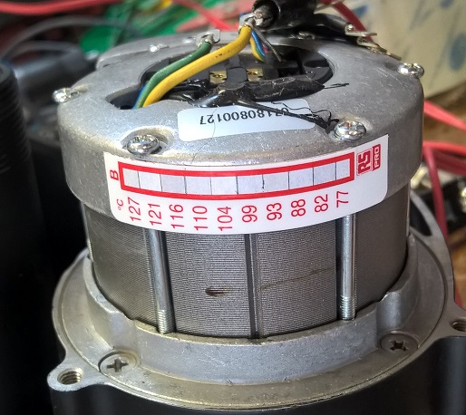
Cooling only front part of the motor itself could create internal hotspots.
We are not talking about chips with nano dimensions for the electronical parts into the chip, but about a relative big laminated iron core.
The sheets you are talking about are so thin for the best contact with the aluminium heatsinck above a chip. The conductivity is higher than grease or glue, that is what they mean with preventing hotspots.
Als for 1mm you need 60 layers of these sheets. Between every layer you got conductivity loss.

The iron core can conduct the heat relative easy, but the air gap is not, so the heat stays in the motorcasing.
So fill the air gap with copper or aluminium is the easiest way.

Motors are known to have internal hotpots.

The plan was to use some compressible 5-6mm adhesive pads to reach and align with the circular part of the cover above the terminals before attatching adhesive PGS strips on top of it extending from a laminated core for more direct heat flow.

It can be hard to get sufficient pressure on to the copper and aluminium plates to eleminate all the possible gaps while taking into account different expansion rates between the steel laminated core and copper or aluminium. Copper and aluminium also might require application of thermal paste which may dry out or migrate.
Copper sponge might not have enough sufficient direct surface area due to uncertainty of distribution of different strands.

Theoretically thick flexible OFHC copper foil could be used instead of the PGS, that would require thermal epoxy which can loose its integrity below zero degrees Celsius or thermal pads which require even pressure around the motor.
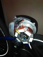
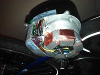
 

Attachments

  • motor-cad_iemdc_2003.pdf
    1.1 MB · Views: 410
It all depends what you want to archieve.
You can made an improvement comparing with the original situation you have now.
Or you want the best thermal conditions for the motor, regardless of the costs.
I think that every improvement is better than it is now.
The most simple improvement is filling the air gap with thermal conductive material.

There are now several practical thermal options published.
All claim an improvement with lowering the motor temperature.

- Copper plates and copper fins on the motor
- Cheap silicon pads between the motor and outer case and aluminium fins outside the case
- Expensive GP extreme pads between the motor and outer case to fill the air gap
_______________________________________________________
eyebyesickle wrote:

I use 12 Wm/K GP extreme thermal pads... and GP extreme thermal grease too...they both seem to have the highest Wm/K rating for a readily available retail/product.

Just more detail, since im slow with the pics...

qty: 4 - GP extreme 40x80mmx3mm - one gets cut longways in half, and wrapped around middle of motor, then the next two stay whole and wrap around the motor. the ends dont touch - they dont fully encapsulate the motor, which is fine, because one side of the motor does not touch the motor housing side - it faces the controller. this is also where I install a temperature sensor.. the last one gets cut into strips and lays around the circular edge in the motor housing cover.

qty: 2 - GP extreme 40x80x2mm - one lays flat in the middle of the circle in the motor housing cover, the other is chopped into strips, and stacked on the 3mm strips around the edge of the motor housing cover, to make it 5mm.

qty: 1 - gp extreme thermal grease - luuuuuuuuube up the sides (doesn't take much)
 
Elinx said:
It all depends what you want to archieve.
You can made an improvement comparing with the original situation you have now.
Or you want the best thermal conditions for the motor, regardless of the costs.
I think that every improvement is better than it is now.
The most simple improvement is filling the air gap with thermal conductive material.

There are now several practical thermal options published.
All claim an improvement with lowering the motor temperature.

- Copper plates and copper fins on the motor
- Cheap silicon pads between the motor and outer case and aluminium fins outside the case
- Expensive GP extreme pads between the motor and outer case to fill the air gap

I guess there's no pic of the last option? If I could run this motor high all the time I agree it'd make it a new motor.
 
Aquakitty said:
............
I guess there's no pic of the last option? ......
Be patience. eyebyesickle said:

"Guys, I'm working on a short article for the cooling of the TSDZ2..."
"......, but I'll write an article by this weekend or so, with pics,....."
"Just more detail, since im slow with the pics..."

So keep an eye on his posts.
 
Because the thermal improvements are not all placed in this topic, I give links to them.
On the New "TSDZ2 Torque Sensor Central Motor" topic there was also some interesting discussion and some solutions mentioned too

This is imho the first solution that came from QuirkyOrk with Silicon pads and aluminium finns
https://endless-sphere.com/forums/viewtopic.php?p=1487260#p1487260

QuirkyOrk writes:
"These two things have made a huge difference. I pushed the motor extremely hard on my commute yesterday at 4x power multiplier and it never got above 58C. Before when I would use the bike at a much lower assist level I would be right below 75 by the time I got to work. "

file.php


This is the the solution elfino has made
https://endless-sphere.com/forums/viewtopic.php?f=30&t=93818&start=3675#p1496647
A solution with cheap silicon pads again, used smaller non sticky pads of 20mm and tape. Both with unknown heat conductivity value
elfnino claims good results last summer (<55 degrees C)

[img=https://endless-sphere.com/forums/download/file.php?id=259096][/img]
 
Elinx said:
Aquakitty said:
............
I guess there's no pic of the last option? ......
Be patience. eyebyesickle said:

"Guys, I'm working on a short article for the cooling of the TSDZ2..."
"......, but I'll write an article by this weekend or so, with pics,....."
"Just more detail, since im slow with the pics..."

So keep an eye on his posts.

Ooops! Thanks for the update.
 
Tried out some crude experiment with homemade 20x55mm copper foil strips containing encapsulated/laminated 1850 W/m.K pyrolytic graphite for better z axis thermal conductivity attached by rubber bands to an aluminium can 70mm in diameter and 40mm in height and compared the temperature rise while pouring boiling water in the can. The one with pyrolytic graphite reached 56 degrees Celsius, copper only 48 degrees Celsius, aluminium 40 degrees Celsius. Measurements were done using thermocouple wrapped in the same foil which was under the test.
 
sysrq said:
Tried out some crude experiment ........
Nice expreriment you did :) You have some pictures too?
What is the size/thickness/mass of all these materials you had measured?
Do I understand you well that you measured:
copperfoil attached on both sides of pyrolytic layer
Pure copper
Pure aluminium
 
Elinx said:
sysrq said:
Tried out some crude experiment ........
Nice expreriment you did :) You have some pictures too?
What is the size/thickness/mass of all these materials you had measured?
Do I understand you well that you measured:
copperfoil attached on both sides of pyrolytic layer
Pure copper
Pure aluminium
Right okay, made some pictures not long ago. Turns out thermal pads on the top should be about 1-1.5mm instead of 3mm, so had to cut them thinner despite the resulting uneven surface. 12W/m.K tacky soft thermal pads on laminated core, stacked adhesive rubbery 6W/m.K thermal pads on the top.
https://www.researchgate.net/figure/Encapsulated-annealed-pyrolytic-graphite-No-shear-transfer-at-interface_fig3_228778400
 

Attachments

  • IMG_20190914_215513_compress6.jpg
    IMG_20190914_215513_compress6.jpg
    147.7 KB · Views: 5,972
  • IMG_20190914_220910_compress39.jpg
    IMG_20190914_220910_compress39.jpg
    280.9 KB · Views: 5,970
sysrq said:
.........
Right okay, made some pictures of not long ago. Turns out the thermal pad on the top should be about 1-1.5mm instead of 3mm, so had cut them thinner despite the resulting uneven surface. 12W/m.K tacky soft thermal pads on on laminated core, stacked adhesive rubbery 6W/m.k thermal pads on the top.
https://www.researchgate.net/figure/Encapsulated-annealed-pyrolytic-graphite-No-shear-transfer-at-interface_fig3_228778400
:bigthumb: Wow, thank you.
These pictures I hadn't expected. Only the experiment
I think I understand now what you have done. Please correct me if I am wrong.
You have placed conductive material around the laminated core, pressed with an alu ring
Between that ring and material you have sticked the pyrolytic material to transfer the heat to the top of the motor
(I saw in the link that the XY conductivity is the biggest)
On top you made contact with the outer casing with conductive pads.

Out of interest.... Have you made that ring/clamp yourself? Or is this an existing one?
 
Elinx said:
sysrq said:
.........
Right okay, made some pictures of not long ago. Turns out the thermal pad on the top should be about 1-1.5mm instead of 3mm, so had cut them thinner despite the resulting uneven surface. 12W/m.K tacky soft thermal pads on on laminated core, stacked adhesive rubbery 6W/m.k thermal pads on the top.
https://www.researchgate.net/figure/Encapsulated-annealed-pyrolytic-graphite-No-shear-transfer-at-interface_fig3_228778400
:bigthumb: Wow, thank you.
These pictures I hadn't expected. Only the experiment
I think I understand now what you have done. Please correct me if I am wrong.
You have placed conductive material around the laminated core, pressed whit an alu ring
Between that ring and material you have sticked the pyrolytic material to transfer the heat to the top of the motor
(I saw in the link that the XY conductivity is the biggest)
On top you made contact with the outer casing with conductive pads.

Out of interest.... Have you made that ring/clamp yourself? Or is this an existing one?
The ring/clamp is handmade.
 
Elinx said:
sysrq said:
The ring/clamp is handmade.
Good work, I hope it is possible to publice soon some temperature measurements of the motor too.
I don't have a temperature sensor installed since normally it should be next to the stator windings. Could use standalone one but don't want any more clutter to check all the time while riding. Could use the same multimeter with a thermocouple for testing though. Also don't have any hills in close proximity.
Now waiting for non-adhesive 1.5mm thermal pads so that there aren't any possible air gaps compared to the ones which were made thinner.
 
sysrq said:
...
I don't have a temperature sensor installed since normally it should be next to the stator windings. ..............
Now waiting for non-adthesive 1.5mm thermal pads so that there aren't any possible air gaps compared to the ones which were made thinner.
OK, that explains problably the reason for the experiment, I think.

What I had seen is you transfer all the heat to the top of the case.
Isn't it better to make the airgap on the front a lot smaller to almost closed.
In your case, I think, it isn't necessary to close that gap for maximal contact with the outer-case, but some pads in that gap should IMHO be better than every air gap to transfer the heat.
You could try by hand feel after a ride if the heat transfer on the outer-case is all the same and not only the most at the side off it.
 
Elinx said:
sysrq said:
...
I don't have a temperature sensor installed since normally it should be next to the stator windings. ..............
Now waiting for non-adthesive 1.5mm thermal pads so that there aren't any possible air gaps compared to the ones which were made thinner.
OK, that explains problably the reason for the experiment, I think.

What I had seen is you transfer all the heat to the top of the case.
Isn't it better to make the airgap on the front a lot smaller to almost closed.
In your case, I think, it isn't necessary to close that gap for maximal contact with the outer-case, but some pads in that gap should IMHO be better than every air gap to transfer the heat.
You could try by hand feel after a ride if the heat transfer on the outer-case is all the same and not only the most at the side off it.
Replaced the AAB Cooling 6W/mK pads which were made thinner with generic more pliable Chinese 1.5mm 6W/mK ones. The AAB Cooling 3mm ones tend to crumble under pressure, so will have to be replaced by a double sided adhesive rubber or anything similar since they mainly act as spacers. When riding the usual 70km commute the heat was felt around the circular part of the cover a bit more than before.
 
Again a solution for more control of heat dissipation is published by najbyk here
But this time the publication will be added to the wiki.

https://github.com/najbyk/TSDZ2-cooling/wiki

This time no pads in the air gap between outer case and laminated core,
but an improvement of the heat conductivity from the motor flange attachment, wich is improved with thermal paste and silicon pads on bottom of the motor and as before, pads on top for better heat conductivity to outer case.

Interesting is also the optional cutting of the plastic cover.

68747470733a2f2f692e696d6775722e636f6d2f3234377a52796b2e6a7067
 
Elinx said:
Again a solution for more control of heat dissipation is published by najbyk here
But this time the publication will be added to the wiki.
...............

Wiki page is ready.
I didn't know about this thread before, thank you Elinx.
I also used thermo pads like sysrq, but on both sides of the motor. I put thermal grease in all sensitive connections. I did one test, it looks like I can use 50% more power in a 100% duty cycle. I will do more tests when the weather is better. It's cold now and it's raining.
 
najbyk said:
..........

I didn't know about this thread before,.......
............
This topic is started by adrea_104kg with an extreme modification and is only active if there is a new solution placed here or in another topic. So the messages falling out of sight if there is no activity.
I thought it would be the best if all published solutions are placed in one thread too, so a better comparision is possible.
Beside in the OSF topic, there where discussions in the TDSZ2 topic too, but I linked only to published solutions.

The only thing what is missing is objective measurements. But I think that will not be done so easy.
Most impressions of the better heat management are made by the users self.
IMHO is every solution less or more an improvement above the default TSDZ2.
 
I like using these non reversible labels, especially when you think you *might* have cooked it.
You know just how hot it actually got, not relying on software, not relying on a counterfeit LM35 chip.

https://github.com/OpenSource-EBike-firmware/TSDZ2_wiki/wiki/How-to-install-motor-temperature-sensor#non-reversible-temperature-label

Temperature_Label_on_Motor1.jpg
 
Elinx said:
The only thing what is missing is objective measurements. But I think that will not be done so easy.

I measure this on the bench electrically. It is accurate and reproducible. I will document the method when I have a chance to dig out the motor and gear - the project got stopped halfway through. Anyone wants to know more - ask me.

You need a 10-15A power supply, multimeter, fan for outside cooling of the case (12km/h).

Current is fed through two of the motor windings.

Power =V*I
Resistance = V/I
Internal winding temperatures can be measured by the change in resistance of the windings 0.393%/degC - copper is similar to the PT100 RTD sensor.
 
crun said:
I like using these non reversible labels, especially when you think you *might* have cooked it......
I had thought about these labels too, but found these a bit expensive for such a purpose. Because you must order 10.
Besides RS you can find these labels too at Ebay or Ali. Maybe someone knows a cheaper source.
crun said:
I measure this on the bench electrically. It is accurate and reproducible. I will document the method .........
That sounds good. I hope it could be done and see the differences.
 
crun said:
....
You need a 10-15A power supply, multimeter, fan for outside cooling of the case (12km/h).

Current is fed through two of the motor windings.
....

I don't know if I understand it correctly. You want to pass the current through a non-rotating motor, right? I think that all power will be converted into heat, as in a resistor. In a normally running motor, most of the power is converted into the torque that drives the bicycle wheel, and the rest of the power is changed into heat. This amount of heat depends on the efficiency of the motor. It seems to me that the test should be done on a running motor. Correct me if I'm wrong.
 
najbyk said:
I think that all power will be converted into heat, as in a resistor. In a normally running motor, most of the power is converted into the torque that drives the bicycle wheel, and the rest of the power is changed into heat. This amount of heat depends on the efficiency of the motor.
It is only the heating (loss) component of the motor that we are interested in. Motor efficiency is irrelevant to how well the cooling works i.e improving efficiency is one thing, improving cooling is a totally separate problem, and what we are trying to improve.

This has two parts: Resistive loss in the windings (I^2R) and magnetic (hysteresis) losses in the iron. The first is an absolutely predictable, deterministic, and unavoidable function of the motor current. The second is something we can't easily predict from the little we know. It doesn't matter to cooling.

It makes no difference whether that heat come from a DC current in the windings, or comes from a AC motor controller current+iron loss. It is all heat, and same temperature rise, and it is all in the same basic location within the motor. 10 watts of DC loss makes the same heat as 10 watts of live motor loss.

With DC, we can accurately measure it and know the heat. With the motor control (AC) we can't measure the iron losses (or the mechanical output), so can not know the actual heating input. Also while using DC we can get instantaneous internal winding temperature. (This is important to me, as I want to make a predictive thermal model the firmware can use to know what motor temperature is)

Note that the power dissipation rating of the motor is quite low it is only 10's of watts not 100's (as efficiency is likely to be high at moderate power levels).

You also have to be quite careful and deliberate with current, and watching temperature. As power is I^2R, going from 10A to 12.5A = 50% more heat. 10A to 20A is 4x more heat. (This is why it is a fairly modest current increase can burn out the motor)
 
crun said:
najbyk said:
I think that all power will be converted into heat, as in a resistor. In a normally running motor, most of the power is converted into the torque that drives the bicycle wheel, and the rest of the power is changed into heat. This amount of heat depends on the efficiency of the motor.
It is only the heating (loss) component of the motor that we are interested in. Motor efficiency is irrelevant to how well the cooling works i.e improving efficiency is one thing, improving cooling is a totally separate problem, and what we are trying to improve.

This has two parts: Resistive loss in the windings (I^2R) and magnetic (hysteresis) losses in the iron. The first is an absolutely predictable, deterministic, and unavoidable function of the motor current. The second is something we can't easily predict from the little we know. It doesn't matter to cooling.

It makes no difference whether that heat come from a DC current in the windings, or comes from a AC motor controller current+iron loss. It is all heat, and same temperature rise, and it is all in the same basic location within the motor. 10 watts of DC loss makes the same heat as 10 watts of live motor loss.

With DC, we can accurately measure it and know the heat. With the motor control (AC) we can't measure the iron losses (or the mechanical output), so can not know the actual heating input. Also while using DC we can get instantaneous internal winding temperature. (This is important to me, as I want to make a predictive thermal model the firmware can use to know what motor temperature is)

Note that the power dissipation rating of the motor is quite low it is only 10's of watts not 100's (as efficiency is likely to be high at moderate power levels).

You also have to be quite careful and deliberate with current, and watching temperature. As power is I^2R, going from 10A to 12.5A = 50% more heat. 10A to 20A is 4x more heat. (This is why it is a fairly modest current increase can burn out the motor)

I didn't understand Your idea. I thought Your goal was to determine the increase in motor power after improvement. Testing how much heat can the motor dissipate to the environment is a very good idea. Your method should work fine. Sorry for the misunderstanding.
 
Back
Top