Hardware temperature control tsdz2

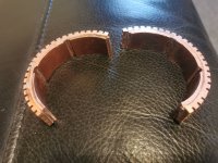
Guys, I'm seeing a different measurement between the motor base and housing, you are using 1.2mm shim but that is too thick and will force the motor to cant slightly unless you are prepared to shim the differnce between the other 2 motor retaining screws that are on the opposite side to the shim material. I measure the gap at 1mm and are using 0.9mm brass shim plate with heat conductive grease on either sides to allow for any casting variances.

I would suggest to actually measure your motor before using 1.2mm by, if you already have 1.2mm, sliding something like a Stanley knife blade across the shim stock and check to see if it will touch the screw mount, if it doesn't then its too thick. Sure you want some clamping if you can, but that will be only on 2 of the mounts, the other two will pull the motor to the post and thus the motor will be on a very slight angle.
 
Waynemarlow said:
...you are using 1.2mm shim but that is too thick and will force the motor to cant slightly .

... I measure the gap at 1mm and are using 0.9mm brass shim plate ....
I would suggest to actually measure your motor before using 1.2mm by, if you already have 1.2mm, ....
Thanks for the warning but....Who is using 1.2mm shim?
Most people use soft 2mm silicon heatpads between motor and housing as described in the wiki by najbyk
Only scianiac has made aluminium shims, but has not mentioned the exact thickness
Famichiki has done measurements for the size of the gap. He measured 1.45mm (without casting burrs)
I understand that you measured a gap at 1mm, which is a lot smaller as Famichiki had measured

Make the hight of the casting burrs that difference?
If so, a Dremel can come in handy or a couple of holes inside the shim.

Your suggestion to measure the size of the gap before using a aluminium or brass shim is a good advice.

file.php
 
I just happen to have one of his plates, and it is about .078" or 1,98mm. I have not taken my motor apart yet to check for fit.

20210130_195425.jpg
 
Vbruun said:
Hi Guys

Just found this thread. Pretty stoked that someone thought my idea was good! I am not planning on building anything in the near future, but maybe When I want to build my next bike?

Anyways, if someone feels inspired to try and change the motor, please do so! I am very interested to see if it will improve anything :)

Very interesting indeed. 8mm shaft seems small, but 3500 watts and 60 amps, might be too much for TSDZ2 frame and bearings, but running at haft that might be fun! I bookmarked incase I destroy my stock motor.
 
Tiger_one said:
.... have one of his plates, and it is about .078" or 1,98mm. ......
That is even almost 2mm instead of 1.2mm.
In that case I understand the concerns of Waynemarlow
 
Elinx said:
Make the hight of the casting burrs that difference?
If so, a Dremel can come in handy or a couple of holes inside the shim.

Your suggestion to measure the size of the gap before using a aluminium or brass shim is a good advice.
The casting burrs were almost non existant on both of the motors I had apart. I used 0.9 shim with a thin layer of high temp thermal conductivity grease on both sides and the motor sat perfectly on its 4 raised mounting pegs having compacted the grease. I do suspect the manufacturers had intended a 1.00m clearance on the raised mounting peg.

I have also used an aluminium sleeve of just the right sze to fill the void between motor and case, simply turn it under size to the motor end rings, cut it lengthwise, place 2.5mm pads on the motor windings section which is hollow in comparison to the end rings, prise apart slightly to slide the sleeve over the motor, let it go and the sleeve will now grip the end rings under slight tension and squash the pads. HT thermal grease around the outside of the sleeve, slide the cover over and job done.

I took a motor cover off after using the motor and the grease had made an almost perfect fit to the case, any slightly undersize voids.

Sadly I do not have a temp sensor on the motor, as all my motors are 6 pin to check on the validity of the mod.
 
What is the O.D. of the end caps on the motor.? Think I might have some T6 to do that, looks like about 2.5".
 
New to this forum (first post) I have made copper inserts to fit in the 6 spaces surrounding the motor (1.5mm thick) and then made a 20mm wide collar of the same 1.5mm copper to wrap right around the motor (inserts soldered to inner surface of collar) and have just ordered some self adhesive copper heatsink (4mm thick) to wrap around the whole thing, hopefully this will lower the temperature enough to stop it overheating more pics to follow when heatsink arrives
 

Attachments

  • Screenshot_20210202_233515_com.ebay.mobile.jpg
    Screenshot_20210202_233515_com.ebay.mobile.jpg
    49.9 KB · Views: 3,162
  • IMG_20210131_162329.jpg
    IMG_20210131_162329.jpg
    132.4 KB · Views: 3,162
  • IMG_20210207_154029.jpg
    IMG_20210207_154029.jpg
    154.7 KB · Views: 3,039
Robcaio said:
... copper inserts to fit in the 6 spaces surrounding the motor (1.5mm thick) and then made a 20mm wide collar of the same 1.5mm copper to wrap right around the motor (inserts soldered to inner surface of collar) .... self adhesive copper heatsink (4mm thick) to wrap around the whole thing,....
Thanks for your contribution
If I understand right, you have filled the 20mm space with 3mm copper and a clamp and want to stick 4mm heatsinks on outside of the tsdz2. What do you plan to use for the contact from the bare motor with the outer case? thermal paste, pads?

Edit:
I didn't understand right how you will use the heatsinks
See you have explained here
 
I'm still work in progress, turned T6 aluminum, 2.950" OD and 2.753" ID. Motor flanges are about 2.750" O.D. but the case cover is on a slight taper, having to do some sanding of my pieces (cut the sleeve in half), but a pretty good fit. I also installed the shim pictured above after sanding it down some. Motor still is slightly above frame, but 3 screws catch it so I think it does stay square. May have to take out and adjust after getting the case back on to fit out.

Getting into the controller and soldering the temp sensor is going to be the hardest job for me.

20210203_161834.jpg
Got it soldered. Spliced sensor to throttle cable, so I can change back to throttle in the future if I want. Soldered pos+ and gnd- to the pads beside the white and black cables after verifying they were indeed the pos and gnd. Covered the area with automotive high temp silicone.
20210203_182211.jpg
20210203_182518.jpg

JBweld sensor to the motor flange so it will clear the shim.
20210203_205312.jpg
 
Sorry forgot to mention you need to taper the last section of the sleeve. I brought my sleeve out to include the outer motor end as well. By accident the taper on mine ended up as an interference fit to the outer case so I should get good conductivity at that point.

I had to make 2 having made the same mistake as yourself, as in not having a taper, but chopped the first into suitably sized pieces to infill the motor winding sections, rather than use pads.

By luck I had a piece of Ali tube of almost the correct size which saved a lot of machining. I”ll measure it up later and post it up.
 
Thanks for that. I only had a piece of round solid scrap so was not long enough to get the entire motor. I put trig to the taper and got about 1.5 degree taper.

I only used 1 of the cut halves as the bottom right half does not touch the case when installed. May use the other half on my next build for the wife.

Good to know on the tubing size, I had too little and too big.
 
Bit of an update...... Heatsink copper arrived today, bit more fiddling and soldering and its together, bit of a cock up on measurements though..... Should have got 3mm not 4.........The cover won't go over it now 🙄
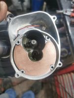
, so it's going to be time consuming job thinning it down to fit, on a plus side I should be able to get good heat transfer through to the outer casing now.
 

Attachments

  • IMG_20210208_170333.jpg
    IMG_20210208_170333.jpg
    326.2 KB · Views: 3,019
  • IMG_20210208_170407.jpg
    IMG_20210208_170407.jpg
    228.7 KB · Views: 3,019
  • IMG_20210208_170432.jpg
    IMG_20210208_170432.jpg
    185.6 KB · Views: 3,019
I like your copper approach. If you have a lathe, might construct an arbor to mount the copper to (same size as motor) and clamp or glue to arbor, take light cuts with lathe to final O.D. of about 2.940" and it should fit.

Case has a taper of 1.5 degrees starting at about the end of the inner flange, or just as your piece begins.
 
Robcaio said:
Bit of an update...... Heatsink copper arrived today, ....
Now I understand how you use the heatsink. :thumb: It a pity that the total height is too much.
Maybe better was to skip the massive 1,5mm plate between the heatsinks and soldered spacers?

I see that you have added a picture of a copper heatplate too on your last message. Can you give the thickness of it? (1,5mm too?)
 
Elinx said:
Robcaio said:
Bit of an update...... Heatsink copper arrived today, ....
Now I understand how you use the heatsink. :thumb: It a pity that the total height is too much.
Maybe better was to skip the massive 1,5mm plate between the heatsinks and soldered spacers?

I see that you have added a picture of a copper heatplate too on your last message. Can you give the thickness of it? (1,5mm too?)
Yes copper plate is 1.5mm as well..my thinking with the extra mass of copper it will draw excess heat away from the windings. Ideally I would like to create airflow through the casing but living in Wales this isn't really an option(wet and muddy)
 
Robcaio said:
..... the extra mass of copper it will draw excess heat away from the windings. Ideally I would like to create airflow through the casing ....
You haven't thought about the airflow outside the case? Sticking external heatsinks there is easier
 
Ride today: Outside 17c (63f)
I'm set on 800watts and 15amps max, Power Assist mode
display 3 data
1. motor temp 62.4c for most part
2. battery voltage 50.6v near finish started with 52v
3. battery current most times when I checked around 4amps (level 2 assist or tour)

13.5 miles, Max speed 23.6mph, Ave speed 17mph, 49minutes total
High temp was 62.8 this in assist level 2 (tour)

For someone more familiar with the VLCD5, last half of ride EO6 started showing and I could not get out of that or show my 3 data??? I did have in advanced on configurator "Temp error with min limit" which was 65 max 80. I'm confused when the E06 comes on, the min or the max setting?
 
Waynemarlow said:
Not necessarily so, you can toggle the setting to only come on when it reaches the max.
May do that on next flash, set the minimum to 70c on this flash. Also took my motor out and sanded down the insert .040" or so, and this time thermal paste that just came in the mail. Applied thermal paste to the half round sleeve inside and out where it touches the motor and housing.

Made cutout for insert in some oak, about .040" deep. 80 grit on knife grinder.
20210217_130240.jpg
 
Elinx said:
Waynemarlow said:
...you are using 1.2mm shim but that is too thick and will force the motor to cant slightly .

... I measure the gap at 1mm and are using 0.9mm brass shim plate ....
I would suggest to actually measure your motor before using 1.2mm by, if you already have 1.2mm, ....
Thanks for the warning but....Who is using 1.2mm shim?
Most people use soft 2mm silicon heatpads between motor and housing as described in the wiki by najbyk
Only scianiac has made aluminium shims, but has not mentioned the exact thickness
Famichiki has done measurements for the size of the gap. He measured 1.45mm (without casting burrs)
I understand that you measured a gap at 1mm, which is a lot smaller as Famichiki had measured

Make the hight of the casting burrs that difference?
If so, a Dremel can come in handy or a couple of holes inside the shim.

Your suggestion to measure the size of the gap before using a aluminium or brass shim is a good advice.

file.php

Just had a test today with the mod suggested by Sceniac (alumiunium shim). I did buy one from his website and it was measured to be just about 2mm. The issue is that it doesn’t fit and causes the cover to not fit properly. Luckily I knew a machinist who could remake it at 1mm and it fits perfectly. The cover fits with a little bit of additional pressure. Temp didn’t go past 50 degrees Celsius pedalling hard for 10-15 minutes. (At about 28 mph).

So just a heads up for anyone wanting to go the alumiunium shim way. (You do also need the thermopads on top as well as thermal paste as per wiki)

Edit: just saw on the web page from where I bought the shim that there is a version 2 that is 1.6mm. However I still think it is too thick as when we measured the depth it was about 1mm, and the shim was about 1 mm (possibly 1.1mm) with thermal paste it did get enough clamping.
 
I'll be honest this ended up being more complicated than I originally planned, but what doesn't. From my original measurements and from some others I thought about 1.5-1.6mm would provide enough spacing to really clamp the plate in there which provides maximum thermal performance. Well I made some in 1mm and 2mm because that was the material available and the 2mm seemed better so that's what I went with, and in my rush to test it I didn't notice the tiny gap that was covered by the thermal paste that is wedges the motor cover out slightly, until someone pointed it out a later. Then I got some 1.6mm material which I think is the ideal balance of the two but at this point IDK so I listed all 3 thicknesses and you can take your pick. Sorry for the confusion, complications, etc.
 
Retrorockit has al ready been introduced last summer with his modifications.

Today he placed a picture off it
file.php


Here is a photo of the TSDZ2 heatsink mod ready to be assembled.
3"x1/8" tubing with a gap cut and beveled to clear the capacitor on the controller.
3mm thermal pads behind it. Thermal grease. Slip fit w/o the pads. Tight with them so they're compressed.
A block of wood and a mallet to press it together. Note thermal paste at bottom of ring also.
Bevel the top outer edge to help assembly.


And again the description what he has done for a better heat dissipation
With some more details about the fitting of the additions.
 
Waynemarlow gives a detailed description of how to improve heat dissipation by machining an aluminum pipe to fill the airgap between motor and casing.
Below you find a short impression of this addition. The complete description you find inside the given link.

If you take a 76mmx 3.2mm Ali pipe and cut it to 80mm in length. Mount it in the lathe and reduce the thickness to 2.2mm. At the outer end make a 8 degree chamfer cut back 15mm. Cut to a length of 38mm and now slit lengthways. Thats your outer sleeve as in the picture.

Now the remainder in the lathe, reduce to 2mm thick and cut it to 21mm in width. Now cut 6 sections 30mm long. These sections fit against the windings of motor parted by the long screws which hold the motor together. These don't quite follow the radius so I've been simply compressing them lightly in a vice to fit correctly.

These measurements are for a 36 volt motor,
 
Back
Top