Headway 48v 10ah - EVcomponents.com

Anybody out there ??? ( it's saturday night and i'm all ready to work on this thing.. ! )

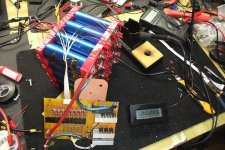
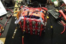
So i soldered all 7 wires, starting at (-) of cell1, problem is that there are 7 bus bars on an 8 cell pack and the last junction is not connected to the 7 wire pigtail...

Logic says i got it wrong, and need to start with ballance wire no.1 at the (+) side of cell 1, this being the 1st junction between cell 1 and 2 ( 1st bus bar ) .

this making any sense ? :lol:

edit : I googled and found this :
http://www.batteryspace.com/prod-specs/356.pdf

Not the same BMS but similar, the wire diagram don't really show me what i want to know..
 
This is what I hate about these BMS boards. Damn poor wiring directions. Wish I could help. barely understand my bms wiring let alone another version.
 
Yeah.. these things are likely childs play for some engineers, but for the rest of us regular everyday normal guys...

Jon Lajoie time :

[youtube]5PsnxDQvQpw[/youtube]

So i went with the logic given 7 wires and 7 junction points in the pack... starting from the negative side at B1...

Crossed my fingers, quick metal game plan involving fire extinguisher in the kitchen near by.. small prayer....
 

Attachments

  • BMS-24v-3.JPG
    BMS-24v-3.JPG
    70.9 KB · Views: 2,561
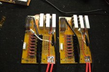
Ok.. so now that the 1st test was a go, i soldered up the 2nd set of ballance wires to the other 8 cells, and soldered some 10g wire to the 2 BMS's i'm going to use.

Now i have to figure out how the hell to wire this up to the black box...

I can either remove the brass lugs on the box cover and install a gromet, then run 2 wires each side for 24v each, one charger per side and connect in series to run the bike

Or, i can have 2 charge wires exit the cover and use the main brass lugs for 48v connected in series inside the box..

Too much Vodka in the system to figure that out tonight.. will tackle that in the morning ! :wink:
 

Attachments

  • BMS-24v-5.JPG
    BMS-24v-5.JPG
    54.2 KB · Views: 2,512
Yet Another Dumb Question Alert!

Maybe I am just out of my league but could I ask yet another dumb question? What are you doing and, more importantly, why are you doing it? Didn't you say that battery came with a BMS? Why are you hooking up 2 BMS's to the battery? Did you remove the stock BMS that came with the battery? Or are you doing something completely different?
 
WonderProfessor said:
Yet Another Dumb Question Alert!

Maybe I am just out of my league but could I ask yet another dumb question? What are you doing and, more importantly, why are you doing it? Didn't you say that battery came with a BMS? Why are you hooking up 2 BMS's to the battery? Did you remove the stock BMS that came with the battery? Or are you doing something completely different?

Wonder no more, i am replacing the original BMS with 2 bigger one's !

The Headway cells are capable of 5C ( 5 x 10ah ) ie: 50 amps, but the original BMS is going into protection mode when it should not.

If you wanted to use this battery in stock form, it would work just fine on a 500w ebike, but this pack is for my e-bmx that has a current limit of 46.5 amps and the original BMS canot cope with this.

The 2 BMS i'm installing now are modified units with a higher power limit, they " should not " shut down even when i crank the throttle from a dead stop, and they work much better at ballancing the cells compared to the original one.

:wink:
 
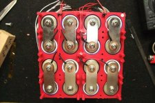
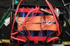
Routed all ballance wires away from the bus bars, i found that using the holes in the red blocks i can zip tie the wires in a bundle, a drop of hot glue on the tail of the zip tie and shove it into the holes for easy removal in the future..
 

Attachments

  • ballancewires.JPG
    ballancewires.JPG
    53.8 KB · Views: 2,429
Ypedal said:
And well.. that kinda sucked....... :(

Quote EVC :
" Built in BMS with max continuous discharge of 60a Max cutoff discharge current 100A "

Well, this is an e-bikekit.com hub motor in a 20" wheel with a crystalyte 35 amp analogue controller, shunt soldered for 45~50 amps on the Cycle Analyst meter..

This BMS does not automatically reset, it requires disconecting the wires and reconnecting.. 1st overcurrent cutout i reset and checked the MaxA value on the CA and it says 36 amps.

I then used up 0.3ah more and managed to cut out on command at low speed ( less than 20 km/h ), if i ginger the throttle to 25+ i can slam the throttle and peak at 50 amps for a moment and then * bzzt.. cutout.

Next step.. solder up the shunt ! :|

Ypedal,

Another good battery test and the first look inside the 48V Headway pack sold by EVComponenets. I wonder though if you contacted the seller regarding the poor performance of the BMS? Are they advertising something they can't deliver (60A continuous/100A max) or did you get a bum BMS? Oh yeah and that little bit of glue to hold the pack in the box with no padding is simply unacceptable!

-R
 
Just thought of something... I work on a military base that does random searches of vehicles. Looking at that battery pack, If I was chosen for a search... my bike would probably be getting blown up at the range.
Looks like some mad scientist bomb.
 
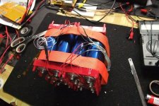
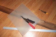
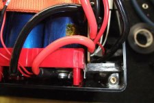
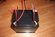
Soldered all the ring terminals and heat shrink added, cut some pieces of Lexan (polycarbonate ) and shimmed all 4 corners of the pack, used industrial hot glue to keep them in place, if i ever need to remove the pack from the box, i can grab these with needle nose pliers and yank them out, but this will keep the pack from shifting inside the box !!!!
 

Attachments

  • Done-2.JPG
    Done-2.JPG
    40.5 KB · Views: 2,891
Took 10 minutes to get the lid on.. but i got it on !!..

pair of charge wires for each 24v pack, going to cut them short to prevent anyone from hooking them up together.....

Back in the backpack, out for a test ride.. I love that feeling of going for a test ride, dark as all hell out there at 6pm but temps are nice at +2 celcius.. :lol:

Plugged in, CA powered up, and away i go...

Project Complete !

Used up 2.5ah as fast as i could, 46 amps sustained and voltage drops to 46.x , no cutouts, no smoke ( yet ). :p
 

Attachments

  • Done-4.JPG
    Done-4.JPG
    39.9 KB · Views: 2,889
EVComponents said:
Lapwing said:
Perhaps in a few months when EV Components has the pick and place machines coping with the demand for there Zilla their might be a niche for a surface mount production version or two. I think that one BMS board aimed at A123-2.3Ah up to perhaps 15ah Headways and a second for the 40-200Ah Sky Energy bricks would sell really well.

As for EV Components and our pick and place machine, it is being used for Zilla production. But it has plenty of spare time to do other things. One of those is a BMS that Otmar (Zilla designer) is working on. Hopefully we will soon have an Otmar approved BMS to offer.

We will likely be seeking some BMS beta testers in the near future.


Well, I think I could fulfill that role... Talked to Stephen last Monday in hopes one of you were going to the Tacoma EV meeting and might be able to bring up a battery pack. Left a message yesterday to see if you were around on Saturday. Let me know if you have a pack available, I just wired up a CA to the kit on my Rans Wave so I could monitor what is really happening.

Scott
 
Ypedal said:
Took 10 minutes to get the lid on.. but i got it on !!..

pair of charge wires for each 24v pack, going to cut them short to prevent anyone from hooking them up together.....

Back in the backpack, out for a test ride.. I love that feeling of going for a test ride, dark as all hell out there at 6pm but temps are nice at +2 celcius.. :lol:

Plugged in, CA powered up, and away i go...

Project Complete !

Used up 2.5ah as fast as i could, 46 amps sustained and voltage drops to 46.x , no cutouts, no smoke ( yet ). :p

Excellent job, Y ! Your hard work has paid off, I think. At least it gives us amateurs some insight into tearing into an EV system and understanding the workings....Much thanks for your leadership!

Overall, do you think it's better to just buy individual cells and add a different BMS? Or start from this and maybe change out the BMS later or right away, like you did...?
 
Hey Sparky ! thx !.

The pack got my ass to work this morning, cranked the throttle full on all the way 5kms, managed to dip to 45v out of the driveway but pack averaged 46~47v at 1000 to 1500w, no drama and all went well..

Depends on your application, the stock BMS imo would be ok with a 20~30 amp controller, my bike needs 46 :twisted: ..

Getting a pre-built unit is a good starting point, for the price you get the lego blocks, bus bars etc, tweak to your hearts content and giv'er !

I'm pretty sure there is enough room in that box for a 60v !!!
 
I'll be interested in how they perform once you get them conditioned.
My 48V (15S) 10Ah LiFePo4 pack is mostly useless after ~8 Amp hrs.
Can't pull 6 amps on the flat or more than 3 up hill.
The BMS kicks off ~43 volts. The CA is set for 45V so it ramps back before the BMS trips.
Resting voltage after 8.78 Ah is 46.6 V.
They aren't Headways and I think they're sucking after only twenty cycles.
EDIT:
I spoke with Justin today and he told me to set the LVC on the CA to 39 volts and let the BMS handle low voltages.
He said I should be able to draw ~9 amp hours at these lower temperatures before noticing a decrease in performance.
We'll see. AFAIC, these batteries are still in a sort of beta testing mode before committing to a fancy housing.
 
Ypedal said:
Was dipping into the 44.x volts at this point at 30+ amps

Hummm, that does appear to be a bit low. I'll be curious to see if those cells can really hold their claimed 60 amps continuous without tripping the LVC...
 
Wait...the pack is not meant for you...amd it says "Ypedal" on the blue tape...holy smokes....there can't be two of you.....I think this pack looks FUN as hell..
 
Got mine today YPedal... drove down to Lacey, WA to pick it up in person. They have those in stock and more... I got a picture of the 20AH pack and it looks a lot more professional than ours. A lot less wasted space and 2ea 5 pin connectors for the power leads along with adapters for wiring it into your system.

I've got pictures here http://picasaweb.google.com/Scott.McElhiney/HeadwayLiFePo4Battery# of the 48V 3A charger they are selling, and of me measuring it charging after it hits green. Also a shot of the 20Ah battery.

Travis might be getting ahold of you for info on the BMS issue. They are very busy working on Zilla controllers but want to resolve the BMS issue with this pack and the smaller ones. The prepackaged setup with the rack is popping the BMS at 10 amps in about 10 minutes, so they aren't shipping them.

I was wondering about what fully charged voltage should be and the pulsing the charger was doing. It hit green at about 54-55 volts, but was still ticking on and off as shown in my pictures. I just got up and the pulsing is gone and I'm about 58 volts. That matches the rating of 3.65v that EV Components lists as the high end of the cell voltage range. I'm wondering if some people getting lower than 10AH out of these are only charging them to 3.3v like the prizmatic cells. Maybe using chargers set for different type of cells.

With a voltage range of 2.5 to 3.65v that means I can drain the pack to 40v safely or is that where the BMS will trip? Maybe I should be setting the CA LVC to 41v or something else?
 
Back
Top