parabellum
1 MW
R=V/I. Resistance is fixed by conductor (we will not get into inductance for now)
If V=12
I=3
R=12/3=4 Ohm
The lower your V= lower your current
If V=12
I=3
R=12/3=4 Ohm
The lower your V= lower your current
parabellum said:R=V/I. Resistance is fixed by conductor (we will not get into inductance for now)
If V=12
I=3
R=12/3=4 Ohm
The lower your V= lower your current
parabellum said:R=V/I. Resistance is fixed by conductor (we will not get into inductance for now)
If V=12
I=3
R=12/3=4 Ohm
The lower your V= lower your current
parabellum said:Here is the heat sink model I was referring to:
http://www.ebay.com/itm/LM2596HV-DCDC-Step-Down-Converter-Adjustable-Heatsink-/261208837194?pt=LH_DefaultDomain_0&hash=item3cd1428c4a
It is considerably more expensive, but you do not need to buy it, just use as reference how to triple RMS performance. You can scavenge aluminum sinks from damaged electronics.
It looks like first value is for V and must move decimal point to the right, second is current Akejanostra said:
In the front of regulator paste can be used, on the back is better to use pads or some other electrical insulator, there are traces under very thin lacquer layer. Keep in mind, you main heat source is regulator chip.kejanostra said:OK, very good idea, thank you for this craftiness!
And, I can added thermal dough before the dissipator, and with which to stick the dissipator?
Thanks. I suppose, after your measurements, you can solder one or few different value resistors with switch, in parallel or series (depends on expected results) to the pot to instantly switch between different torque settings. This is actually unique and only advantage of this motor you want to exploit. Have a good day!kejanostra said:OK, I made the order for this " step-down converter tension ", then later, I would add a small dissipator with thermal dough on him.
Then, I would make the tests for approach a reasonable speed enter 3V and 5V.
And thus, concerning the values indicated on the video above, it is (3V on screen left), and, (0,9A on screen right), that's it?
Thank you Parabellum, and good day to you!
parabellum said:you can solder one or few different value resistors with switch, in parallel or series (depends on expected results) to the pot to instantly switch between different torque settings. This is actually unique and only advantage of this motor you want to exploit
They are kind of small, I believe, and will not increase heat dissipation much if any. Anyway, you will have ~ 1.2A flow at 5V and even less at 3v, it may work for a while.kejanostra said:I did not find small to dissipateur alu in my old devices dead, but I found that:http://cgi.ebay.fr/ws/eBayISAPI.dll...eName=STRK:MEWAX:IT&_trksid=p3984.m1438.l2649
He is good normally, then I go ordered because not cheap for the 5 parts.
parabellum said:For high torque, you can make bypass switch from battery + to rotor+ without torturing this sweet, little converter. It awoids messing and soldering on converter and is even cheaper. What do you think?
parabellum said:P.S. any aluminum piece is potential heat sink! Just cut of a peace of L shaped allu profile. You can go to computer repair shop, old damaged PC power supplys are a treasure chest of heat sinks.
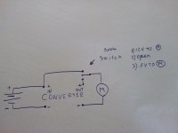
This is a good question! I would just short In and Out on my converters, but they are little different to yours. I do not believe you can damage it this way, but to be sure, you could take 3 way switch and make 1 side connect converter Out to rotor + , middle position all off, and 3rd position Bat+ to Rotor +.kejanostra said:OK, but, if I connect (+ battery and + rotor) on switch (2 positions, that's it?), thus a position for (TORQUE), and a position for (SPEED), then, in position (TORQUE), the rotor will be not fed 12V for (TORQUE), because the small converter tension to feed the rotor with 3V or 5V.
Or then, I connect the wire (+ of converter tension, 3V or 5V rotor) and one other wire coming of rotor for (+ battery 12V - TORQUE) to the switch, and the 2 wires (+) Outgoing of switch, to (+ battery 12V), and so, I have, a position 12V TORQUE, and, a position 3V or 5V (according to my choice V) for SPEED, on my switch.
Or then I includes "NOTHING" and I have to see a plan, because it is better that a big explanation.

parabellum said:you could take 3 way switch and make 1 side connect converter Out to rotor + , middle position all off, and 3rd position Bat+ to Rotor +.
kejanostra said:parabellum said:you could take 3 way switch and make 1 side connect converter Out to rotor + , middle position all off, and 3rd position Bat+ to Rotor +.
Have you a small fast sketch, that I visualize the thing?
parabellum said:kejanostra said:parabellum said:you could take 3 way switch and make 1 side connect converter Out to rotor + , middle position all off, and 3rd position Bat+ to Rotor +.
Have you a small fast sketch, that I visualize the thing?
Yeah. Cool heatsink, you even went into details cutting those wings.kejanostra said:What do you think of my small dissipator, well or well:lol:

Yeah. Cool heatsink, you even went into details cutting those wings.parabellum said:kejanostra said:What do you think of my small dissipator, well or well:lol:
parabellum said:I personally like this one, integrated in the throttle:
http://em3ev.com/store/index.php?route=product/product&path=41&product_id=94
Skalabala said:Yeah. Cool heatsink, you even went into details cutting those wings.parabellum said:kejanostra said:What do you think of my small dissipator, well or well:lol:
And he even did a good job with the deburring!
parabellum said:Yeah. Cool heatsink, you even went into details cutting those wings.kejanostra said:What do you think of my small dissipator, well or well:lol:
As for the switch, you can take:
http://www.ebay.com/itm/Rocker-Switch-3-Pin-250V6A-125V10A-Black-Plastic-3-Way-I-0-II-SPDT-3P-New-/151326053352?pt=LH_DefaultDomain_2&hash=item233bbc53e8
or if you want it with fixture for handlebar.
http://www.elifebike.com/peng/iview.asp?KeyID=dtpic-2011-1A-GDAS.52NPF
I personally like this one, integrated in the throttle:
http://em3ev.com/store/index.php?route=product/product&path=41&product_id=94