((Help me please!! alternator delta conversion as a motor))

Harold in CR said:
I bought a 45A alternator, ($25.00 US)an 80A Mystery ESC ($16.00) and 2 Servo testers, ($8.00) all the electronics same as yours. :lol: When they are delivered to me, I will see if I can duplicate your results. 8)

Thanks for putting so much effort into this project and sharing here.

Harold in CR


Hello Harold in CR,

Normally, you will have no problem, because you have similar that me.
The problèm with the old alternators, it is because magnets stator, as well as magnets of the rotor and rotor tip (where coal rubs), are dirty thickness (they are black), and prevents the voucher work.
Then hesitate not to sand with "wool of iron", then breath with air or brush paint.


PS:You will also need one converter step-down of tension (or 2), because to create your machine tool, you will can fed the rotor with low-voltage (by EX:3 or 5V) and thus more speed, because 12V just give of the " couple, the strength " and little speed.
And so, made as I have make, a small radiator (Dissipateur) aluminum, and the stuck with strong thermal dough on the regulator (small chip square and black), you can have good performance then.(Thank you for this information Parabellum).
You go to laugh! But at the beginning of my conversion alternator, how her worked not, me to believe that everything materials electronics of the Chinese sellers were failing, then I sent messages to them to indicate, and, them still sent back everything towards me, COOL!, and meanwhile, my conversion worked! :lol:
The cause: magnets stator, magnets and centres rotor were with a big thickness black, thus no possible magnetism.
But in reality, the total cost returns to approximately $50 (without battery).
And with battery 12V lithium (slight), the total cost is approximately $80.Alternator is free for me, I have the old alternators free, because I change to people a new alternator.
Look this link, it is small price:
http://cgi.ebay.fr/ws/eBayISAPI.dll...eName=STRK:MEWNX:IT&_trksid=p3984.m1439.l2649

Good day! :wink:
 
kejanostra said:
I crossed a few hours to make this plan, then he is correct?
Thank you. :wink:

Real life things got in my way for few days, but Im back again.
1)This A switch(looks like you want to use it over your throttle) will not work for ESC, it must be some 80A capable switch, relay or manual connectors (for ESC you have).
2)Your ESC has no current limiting and conductor on the "motor" is way to tough for it( I believe), you probably will burn the ESC in low speed high current event, CA3 is not cheap but will limit battery current and as consequence phase current, keeping the system alive for long time (Limiting current on some 80/3 A). Other solution is to by some >200A esc, but still not fool proof.
3)You need cooling on the ESC, or temp sensor for temperature monitoring, better both.
 
parabellum said:
Real life things got in my way for few days, but Im back again.
Hello! I hope nothing nasty for you? :shock:


parabellum said:
1)This A switch(looks like you want to use it over your throttle) will not work for ESC, it must be some 80A capable switch, relay or manual connectors (for ESC you have).
I asked myself the question on this button,
Because he would have allowed to pass the current only of 6A 250V-10A 125V.
As this one, he is good?
http://cgi.ebay.fr/ws/eBayISAPI.dll...eName=STRK:MEWAX:IT&_trksid=p3984.m1438.l2649

parabellum said:
2)Your ESC has no current limiting and conductor on the "motor" is way to tough for it( I believe), you probably will burn the ESC in low speed high current event, CA3 is not cheap but will limit battery current and as consequence phase current, keeping the system alive for long time (Limiting current on some 80/3 A). Other solution is to by some >200A esc, but still not fool proof.
I not knowledge of this component "CA3", he must be connected where, and where to buy?

parabellum said:
3)You need cooling on the ESC, or temp sensor for temperature monitoring, better both.
I was going to make good heat dissipateur on ESC.

PS:Otherwise, the principle of my plan is good, no?
 
kejanostra said:
As this one, he is good?
http://cgi.ebay.fr/ws/eBayISAPI.dll?ViewItem&item=201110476153&ssPageName=STRK:MEWAX:IT&_trksid=p3984.m1438.l2649
I do not know what this switch does, there is no description, but it definitively does not cut Bat+ to ESC+. Use 12V car relay trigered by your little switch over throttle or just use 60 or 100A circuit breaker, like following or what ever you get where you live.
http://www.aliexpress.com/store/product/1P-100A-240V-415V-50HZ-60HZ-Circuit-breaker-MCB-sp/613696_623616656.html

CA3 is:
http://www.ebikes.ca/product-info/grin-products/cycle-analyst.html
There are piles of treads about on ES. V3 has ESC PWM output, you do not need servo tester anymore, just throttle-CA3-ESC. You will need Stand Alone version with shunt and sped sensor, then you are set and secure.

P.S. I was hesitating about my first CA, thinking it is expensive toy, now I have 3 of them, 1 is still in the box for over 1 year :D, no I will not sell it, my precious.
file.php
 

Attachments

  • download.jpg
    download.jpg
    7.7 KB · Views: 2,101
That rotor does not have the magnets pinned or screwed fast to the hub. It's made for slow rpm's as a wind turbine or hydro turbine, perhaps 1000 RPM's max.
 
parabellum said:
I do not know what this switch does, there is no description, but it definitively does not cut Bat+ to ESC+.

Nevertheless, he(it) is planned to light / put out for ESC until 150A.


parabellum said:
CA3 is:http://www.ebikes.ca/product-info/grin-products/cycle-analyst.html
There are piles of treads about on ES. V3 has ESC PWM output, you do not need servo tester anymore, just throttle-CA3-ESC. You will need Stand Alone version with shunt and sped sensor, then you are set and secure.

I saw a guy on one site, which uses a tester of servo with LCD screen which gives the information watt, ampere, etc., and he connected the wires handle throttle inside, then he works very good and simillaire to CA3, but 3X cheaper than this CA3.http://www.bitzracing.com/EV/razor/
But I, I veus not launched so much money in this small project, because my purpose, and to make exactly one undid project for cheap, you understand?
Because ensute, people who have not enormous money can make also.

PS:
The ESC 80A, delivers only at its exit 80A, to the engine (Alternator or Brushless rc),
but, it does not need of 80A, on red and black at its entry?!
Then I includes not why, my on/off switch, not not allowed to pass the current 12V, to entry (+ and-) ESC.
 
kejanostra said:
parabellum said:
I do not know what this switch does, there is no description, but it definitively does not cut Bat+ to ESC+.

Nevertheless, he(it) is planned to light / put out for ESC until 150A.


parabellum said:
CA3 is:http://www.ebikes.ca/product-info/grin-products/cycle-analyst.html
There are piles of treads about on ES. V3 has ESC PWM output, you do not need servo tester anymore, just throttle-CA3-ESC. You will need Stand Alone version with shunt and sped sensor, then you are set and secure.

I saw a guy on another forum, which uses a tester of servo with LCD screen which gives the information watt, ampere, etc., and he connected the wires handle throttle inside, then he works very good and simillaire to CA3, but 3X cheaper than this CA3.
But I, I veus not launched so much money in this small project, because my purpose, and to make exactly one undid project for cheap, you understand?
Because ensute, people who have not enormous money can make also.

PS:
The ESC 80A, delivers only at its exit 80A, to the engine (Alternator or Brushless rc),
but, it does not need of 80A, on red and black at its entry?!
Then I includes not why, my on/off switch, not not allowed to pass the current 12V, to entry (+ and-) ESC.

1)Switch on the link does not have cabling nor size to bare with 150A, it may SURVIVE 15A for 1 minute but I would not expect it as well.
2) You do not need CA to see fancy numbers and statistics, you need something to limit current! If your current goes over the limit FETs in ESC can handle just for instant, buy buy ESC. I have a pile of burned 100A and 200A ESCs in my junk box. This pile is far more expensive then 1 CA.
3)All cabling, contacts and switches must be rated to take current you want to push. It is about resistance, if wire resistance is hi it heats up and and burns insulation, then shorts to another wire taking down your ESC and shorting battery in worst case. If switches contacts and contacting area is to small, it heats, burns everything around it with potential of a long list of consequences.
You will find out soon that spinning a generator on the bench is very different to propelling few hundred pound around.

Gentleman's, do not expect much of this generators, they may be good solution to generate some charge for your battery, but very poor and inefficient motors.
Harold, I do not want to disappoint you, but this whole generator is more a heater at higher ERPM, due to Eddy Currents generated on those thick lam stacks. :D
 
parabellum said:
Gentleman's, do not expect much of this generators, they may be good solution to generate some charge for your battery, but very poor and inefficient motors.
Harold, I do not want to disappoint you, but this whole generator is more a heater at higher ERPM, due to Eddy Currents generated on those thick lam stacks. :D

http://www.industrial-scientific.co...cations_for_Alternator_Converted_to_Motor.htm


It is only a "test" at the moment, and I do not wish to make the running against a ferrari my friend.
But he is sure, afterward, that all the wires will be secured with a big wires to avoid burning, and I would add all the same a young cut circuit breaker 100A domestic (if I find one) on the way out of the battery, then I go me informed for a simple solution and not high price, to limit the current towards FET ESC.

Parabellum, if it annoys you to participate on this thing, useless to tire you to answer, I understanding well. :wink:
 
kejanostra said:
Parabellum, if it annoys you to participate on this thing, useless to tire you to answer, I would understand.
No, my friend, it annoys me to realize your disappointment at end of the hard work you are putting in, being my fault overlooking some failing aspect of your design, after taking this responsibility. :)

I would rip all hairs out of my ass to make something useful of a generator rusting in my backyard doing nothing (motor conversion is the first thing I consider), but I would not purchase it as motor substitute in mind. 61% efficiency in your link is just acceptable as toy purpose, not transportation solution. I know you got it for free, that why I share your enthusiasm. :wink:

P.S. 30% of Li battery cost in my moped is actually much higher then 100% of the motor cost.
 
parabellum said:
I would rip all hairs out of my ass to make....
And they grew again since? :lol:


parabellum said:
P.S. 30% of Li battery cost in my moped is actually much higher then 100% of the motor cost.
Yes, it's true, the prices concerning Lithium batteries and charger are very high. (According to the Voltage wish).

Then otherwise, I hesitate between circuit breaker 100A and that:
http://www.aliexpress.com/item/Rela...lay-100A-Relay-12V-Relay-5PINS/874101590.html

This relay seems the shit to be connected with 5 brooches! But he is 12V 100A, that to make?
Would I do can connected my switch on/off ( A ), before this relay, then relay towards all the rest?
 
kejanostra said:
Then otherwise, I hesitate between circuit breaker 100A and that:
http://www.aliexpress.com/item/Rela...lay-100A-Relay-12V-Relay-5PINS/874101590.html

This relay seems the shit to be connected with 5 brooches! But he is 12V 100A, that to make?
Would I do can connected my switch on/off ( A ), before this relay, then relay towards all the rest?
This one looks good. You only need the relay to disconnect battery from ESC, so there is no parasitic drain while you do not use your system, rest of your low current electronics can be interrupted by switch (on relay coil input) or by relay itself (on ESC input). Just try not to go over half of the switch rating, they usually do not live long on max current.
 
parabellum said:
You only need the relay to disconnect battery from ESC
OK, but I would be obliged to disconnect with the hand, it is boring, because I wanted a button to put in-out (switch on-off) supply battery towards ESC. :(


parabellum said:
rest of your low current electronics can be interrupted by switch (on relay coil input) or by relay itself (on ESC input).
OK, It is thus necessary to redo all my plan, because nothing more goes now.
Not easy also, to spot on this relay for connected, the shit that! :(


parabellum said:
Just try not to go over half of the switch rating
I could not overtaken half of the current for switch (6A 250V - 10A 125V), that's it about which vouv want spoken?.
Of all the manners, only the supply for the rotor will get through the switch, thus, just 12V and 3A for Couple, then between 3 and 5V and approximately maybe 2A for speed, then the current will be in half, no? :roll:
 
kejanostra said:
parabellum wrote:
Just try not to go over half of the switch rating

That is? Not good understood.
If switch is 6A rated, try to have 3A or less going trough. Remember DC current is hard to interrupt.
kejanostra said:
parabellum wrote:
You only need the relay to disconnect battery from ESC

OK, but I would be obliged to disconnect in the hand, it is boring, because I wanted a button to put out (switch off) supply battery towards ESC.
I do not know what you mean here. You can have just a connector you can unplug manually, it is very uncool to do in front of people, but it works fine. If you switch rest of the electronic (mostly rotor exciting) off by the switch, you can let it plugged in (I do not think brain and caps drain that much), until you are home.
 
parabellum said:
I do not know what you mean here. You can have just a connector you can unplug manually, it is very uncool to do in front of people, but it works fine.

In my precedent message, I badly expressed myself, I wanted to say:
I veus to put out(switch off) with a button, and I wish not disconnected manually a wire to put out (switch off).
If that there could be OK for battery and ESC, it would be better towards the handlebars.

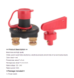
http://www.aliexpress.com/item/For-...-Off-Isolator-Ignition-TT2951/1621683840.html
:wink:
 
kejanostra said:
parabellum said:
I do not know what you mean here. You can have just a connector you can unplug manually, it is very uncool to do in front of people, but it works fine.

In my precedent message, I badly expressed myself, I wanted to say:
I veus to put out(switch off) with a button, and I wish not disconnected manually a wire to put out (switch off).
If that there could be OK for battery and ESC, it would be better towards the handlebars.

http://www.aliexpress.com/item/For-...-Off-Isolator-Ignition-TT2951/1621683840.html
:wink:
Yeah, that switch is cool, it is actually a key lock, take key with you and nobody can mess with your...? What are you doing? Is it a bike? . Do not forget to keep your power wiring as short as possible.
 
parabellum said:
Yeah, that switch is cool, it is actually a key lock, take key with you and nobody can mess with your...? What are you doing? Is it a bike? . Do not forget to keep your power wiring as short as possible.


Oh you know, here everybody knows who is whom in my perimeter, and nobody steals things, I thought of this thing there, because I did not find small switch 80-100A, and just he is simpler to connect on him, and also give better comfort than with relay or to disjonteur, and he is planned for work on 12V 100A (battery to ESC 80A), that's it.
Thus, how you say Parabellum, I have to put the wires closer possible of the battery?That's boring, Because I wanted to put everything switch etc., on handlebars to be comfortable.
What kind of wires do you do recommend me Parabellum? Because I thought of the wires is domestic (copper and stiff), or, son as classic electric extension lead (braid copper and souple - 2,5mm-3mm).

I wish installed on one as him :

View attachment 1

PS:I found switch (on- off) 12V-100A, even better price, with shipping free.
http://www.ebay.fr/itm/12V-24V-100A...8300?pt=JG_FR_Auto_Pièces&hash=item54084675ec

Picture:
switch 12V 100A.png
 
kejanostra said:
Thus, how you say Parabellum, I have to put the wires closer possible of the battery?That's boring, Because I wanted to put everything switch etc., on handlebars to be comfortable.
What kind of wires do you do recommend me Parabellum? Because I thought of the wires is domestic (copper and stiff), or, son as classic electric extension lead (braid copper and souple - 2,5mm-3mm).
You have actually Low V and high Current setup. Cables participating in power transmission should be accordingly gauged, it means + and - from battery to ESC (you may know but on your picture -(negative) should go directly to ESC, not crossing thin step down converter traces).
At your Current levels I would start with 5mm2 and up pure cooper wiring. Where I live, classic extensions are nowhere near 5mm2 and nowhere near pure cooper. :D I prefer to take fine multystrand construction cabling, that weights in cooper region (lot of cooper like aluminum on the market) and not magnetic (cheep wire is often some cooper-iron mix). You can also source good thick wire at Car Sound Audio stores, following above rules.
You can install power switch on the handles, but every additional cm of wire is additional heating and efficiency loss.
Next is nice picture of conductor equivalents.
 

Attachments

  • Conductivity1.gif
    Conductivity1.gif
    9.8 KB · Views: 2,037
parabellum said:
but on your picture -(negative) should go directly to ESC, not crossing thin step down converter traces).
Yes, it's true, I had thought in more! Look now at the plan, I modified on him. :wink:

New Plan:


parabellum said:
You can also source good thick wire at Car Sound Audio stores, following above rules.
You can install power switch on the handles, but every additional cm of wire is additional heating and efficiency loss.
Next is nice picture of conductor equivalents.
OK, thank you for the picture and the informations.
If I install all, the 3 switches towards handle, there will be approximately 1,50cm of wire, between switches and engine/battery.
I have audio wires copper, but he is 2mm, I also have cable (starting up car) but him he is too thick and dificile to be connected.
When I would receive all my small commands (switch 12V 100A, battery 12V 9800 mAh Lithium, then 2 small switches), I would make a test on rotor, with my wires audio flexible copper 2mm (3 meters), then I to buy wire flexible copper (4mm) for ESC and battery (3 meters), and I would see if the wires warm.
Now, I go a few days to vacancy to free my head. :mrgreen:
See you very soon.
 
kejanostra said:
New Plan:
Your new plan looks good.
Have you seen this tread?
http://endless-sphere.com/forums/viewtopic.php?f=30&t=61343&p=917145#p916424
Good info here!
My new conclusions: :roll:
1) I believe you need diode on rotor input, because BEMF of the rotor can hammer your converter to died.
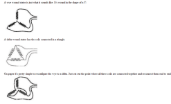
2) You may think of rewiring your motor to star (Y), your KV is divided by 1.73 but efficiency loss in delta (D) on those gens seems a big deal.
 
With a delta connection, picture a triangle. Each side of the triangle is a transformer or motor winding. Call the 3 corners of the triangle A, B, and C. There are only 3 wires except for a safety ground, which has no connection to, nor is any part of, the power transmission service lines.

All 3 windings have the same voltage, say for example 208V. If you take a meter, you will measure 208V between A and B, between B and C, and between C and A.

With a wye connection (also called a star connection) take our triangle above and use your wire cutters (literally) to cut the triangle apart at the corners. rearrange the three sides (transformer or motor windings) to form a Y. Where the three sides join in the center, connect a fourth wire. Call this wire "neutral". Call the three ends A, B, and C. Connect the 3 supply service lines to A, B, and C.

Now if you measure with your meter you will see 120V between the neutral and any single phase (A, B, or C), but you will still measure 208V between A and B, B and C, and C and A. The 208V is used to power three-phase loads and the 120V is very handy if you need to power a 120V single-phase load, such as a toaster! In a wye system, the supply service line-to-line voltage is 1.73 times the voltage from any phase to neutral.

Delta power is used for motors, 3-phase heaters, anywhere you don't need a neutral.

The biggest use of delta is in power transmission. Way too expensive to run a fourth wire all those miles, especially since a 3-wire delta transmits the same amount of power. Look up at a transmission tower and you see three phases and a ground wire for lightning suppression. No neutral.

At the destination, (a distribution transformer outside the home or business), the primary of the transformer is wired delta and the secondary is wired wye. This creates the neutral that can be used to derive single-phase power where needed. The neutral is grounded at the service entrance. Wye systems must be used where you have single phase loads that you must feed.

Interestingly, if you hide the neutral, you really can't tell the difference between star and delta systems. The phase-to-phase voltage is exactly the same. Most of the time 3-phase motors (which are internally delta-connected and have no neutral) are fed from a wye-connected source, simply omitting the neutral.
Technical information

When the windings of a 3-phase motor are connected in STAR:

* the voltage applied to each winding is reduced to only (1 /.'/'3) [1 divided by root three] of the voltage applied to the winding when it is connected directly across two incoming power service lines in DELTA.

#the current per winding is reduced to only (1 /.'/'3) [1 divided by root three] of the normal running current taken when it is connected in DELTA.
# so, because of the Power Law V [in volts] x I [in amps] = P [in watts],

the total output power when the motor is connected in STAR is:

PS = [VL x (1/.'/'3)] x [ID x (1/.'/'3)] = PD x (1/3) [one third of the power in DELTA]

where:
VL is the line-to-line voltage of the incoming 3-phase power service
ID is the line current drawn in DELTA
PS is the total power the motor can produce when running in STAR
PD is the total power it can produce when running in DELTA.

a further disadvantage when the motor is connected in STAR is that its total output torque is only 1/3 of the total torque it can produce when running in DELTA.

Difference between star and delta.
Star generates a high voltage at a low current, and delta generates a low voltage at a high current.

Wye-Delta-Wye Delta.png


Yes, thank you for this thread which gives its experience, but you know, I read a lot of thing on alternator a lot conversion, and all have a different way of making worked.
A lot of people, shows picture, write a lot, but do not really show the thing with an explicit tutoriel, or videos to see, nor explain the thing.
Some make copy/paste picture, information, but they tried nothing on the conversion, then just for make their free publicity to sell!
Me, I have to sell nothing! I am an artist with my hands, but people can make that I to create by looking on YouTube, or on my blog, see you?
I to read little on the net, I make, I show, no lie, and I think that it is necessary to read, to learn and especially, to learn with its made errors.
See you soon dear readers.
 
I do not know what you want to say with your previous post. Info you shared is interesting, more focused from generator and power transmission perspective and not much about efficiency, but anyway.
Anyway, star connection is always more efficient then delta, some motor designs make it big difference in efficiency others not so much and can be ignored.
There are few treads on ES that explain in detail what makes delta inefficient. In short: you have currents running over 2 paths:
1 is direct path over first inductor you actually want to energize
and 2 is over other 2 series inductors, this one is double as resistive way but still. If your EMF shape over those 2 paths does not matches well, recirculating current is created, kind of 1 coil discharging in to other, as result, creating heat=inefficiency.
Some motor designs are not useful in D connection scheme, some are less affected.
It actually depends on poles to tooth relation in my understanding.
You can try both schemes and finally make your conclusions, then maybe share your results here. For star you also need higher V (other controller)to get some power.
 
parabellum said:
I do not know what you want to say with your previous post.

I say that: a stage by stage of this conversion altermotor would be better, that some pictures, some figures, then to disappear, by leaving a link site of sale.
The post does not give "enormously" help for those who really want to understand and to realize this conversion.
But it is my "Opinion".
 
Back
Top