Help with charger for Urban Mover UM44 (kl3688cr3 BMS)

Joined
Jan 23, 2023
Messages
17
Hi all,

I have an Urban Mover (24v). I bought it from a neighbour without a charger. Battery still has charge and works (I've been using it with my electric chainsaw). But I need to sort out the charger.

I bought a new 24/28v ebike charger on ebay but could only find one with a 3 pin plug (mine has a 5 pin plug). So I've ordered a new 5 pin plug to fit onto the charger. Happy to solder the new one on.

Edit: my original list wasn't terribly clear. I know the polarity of the battery output. I don't know the polarity of the charger input (to the battery). The 5 pin plug in the photo is for charging only. Battery output is in a separate port.

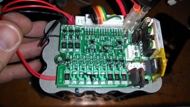
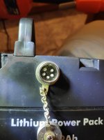
My issue is I don't know which pin on my battery (charger input) is positive and which is negative. On my battery (see photo below) only the two pins on the left hand side (not the lower central one) are connected to anything. Both go to the BMS but I can't tell which is positive. No markings on the BMS.

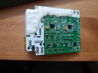
BMS is a kl3688cr3 which I believe is fairly widely used. But I can't seem to find a circuit diagram. I've no reason to believe its not working but can replace if needs be (I've done this before). Photo of the BMS is nabbed from somewhere else online but I've highlighted where the charger cables go to (red highlight - lower right hand corner). There are 4 pins but they're soldered together on the other side in 2 blocks of 2.

Thanks.
kiSnhPf.jpg1674493392559.png
 
UnclePuncher said:
I have an Urban Mover (24v). I bought it from a neighbour without a charger. Battery still has charge and works (I've been using it with my electric chainsaw).
<snip>
My issue is I don't know which pin on my battery is positive and which is negative.
If you don't know which is which, how did you use it with your chainsaw?


To find polarity on any voltage:
Set your multimeter to 200VDC.
Put red lead tip to one of the two possible connector pins you know is connected internally.
Put black lead tip to the other connector pin.
If the meter reads negative - in front of value, then you have them reversed. Swap them, and if it reads the expected voltage with no - sign, then whichever one the red lead is on is positive.


BTW, it's not uncommon for stolen bikes / etc to be sold without chargers (because the charger wasn't with the bike when they took it), so unless you know for sure the bike was theirs....you might have bought stolen goods. (it's happened to people here before).
 
I know the polarity of the battery output but I don't know the polarity of the input (from the charger). Battery output is at the other end of the battery, the photo is just of the charger connection. Obviously I know the polarity of the charger too but not which way round it should connect to the battery.

I bought the bike from a neighbour. It's not stolen. But thanks for your concern.
 
E-HP said:
Sounds like you got all the info you need. Make sure to maintain safe practices while charging! :bigthumb:
Does it? As yet I've got no new information.

I still need to know how to determine the polarity of the charger input to the BMS. That was my original query and I'm no closer to an answer unfortunately.

Tempted to buy a new BMS and install it. But afaik there is nothing wrong with this one. I just don't know how to charge it. No markings on the board and can't find a circuit diagram online.
 
It's a little hard to see in the picture of the BMS, but it looks like there are two spade lugs labeled OUT+ and OUT-. Were there wires hooked up to these?

All of these small BMS units have the positive side wired straight through. The positive battery connection goes right to the output. Switching happens on the negative side. If this is a single port (sort of looks like it), you charge through the same pair of wires as you discharge. Then it's a matter of tracing the wires back to the connector.
 
UnclePuncher said:
Does it? As yet I've got no new information.

You asked this
UnclePuncher said:
My issue is I don't know which pin on my battery (charger input) is positive and which is negative. On my battery (see photo below) only the two pins on the left hand side (not the lower central one) are connected to anything.

amberwolf responded with this
amberwolf said:
To find polarity on any voltage:
Set your multimeter to 200VDC.
Put red lead tip to one of the two possible connector pins you know is connected internally.
Put black lead tip to the other connector pin.
If the meter reads negative - in front of value, then you have them reversed. Swap them, and if it reads the expected voltage with no - sign, then whichever one the red lead is on is positive.

You got the information you were asking for.
 
I didn't though.

They're telling me how to measure a voltage.

My issue is not with measuring a voltage but which way round the charger input should be.
 
fechter said:
It's a little hard to see in the picture of the BMS, but it looks like there are two spade lugs labeled OUT+ and OUT-. Were there wires hooked up to these?

All of these small BMS units have the positive side wired straight through. The positive battery connection goes right to the output. Switching happens on the negative side. If this is a single port (sort of looks like it), you charge through the same pair of wires as you discharge. Then it's a matter of tracing the wires back to the connector.

Thanks. That's actually useful. I'll get the BMS out tonight or tomorrow and have another look. Should be able to get some better photos too.
 
UnclePuncher said:
I didn't though.

They're telling me how to measure a voltage.

My issue is not with measuring a voltage but which way round the charger input should be.
No, I told you how to determine polarity (in a safe and easy way), which is what you need to determine.
 
There will be voltage present on the charger input unless the BMS is disconnected. Normally it would read the same as the pack.
Thanks.

I wasn't aware this was the case. Should it be the same voltage as the pack. I'm getting nothing on the two charger pins.

BMS is connected.
 
OK, just tried again but with the multimeter set to 20vdc (not 200vdc). I get a tiny voltage (less than 1v) does that sound about right? Wasn't showing up on 200vdc.
 
Something's not right there. You could measure each wire from the controller negative wire. The positive side of everything should be connected together.
 
Assuming you have the connector plugged back into the BMS (I'm presuming per your note in the first post that it plugs into the four pin connector you have circled in this image:
https://endless-sphere.com/sphere/attachments/1674493392559-png.330166/ )
then:

Unless the BMS has turned the charge port off because the pack is:
--over it's full charge limit (either for one cell or the pack as a whole)
--there is a problem with a cell or cells that is outside the allowed limits
--the charge port has failed in some way
--some other problem has occured that the BMS sees outside the safe recharging limits
or there is a broken wire, poor solder joint, or bad crimp somewhere between the BMS and the connector, then you should read the same voltage on the charge port as the discharge port, for the common BMS designs.

If they used a protection diode between the charge connector and the BMS's charge port (rare, but some have) then there will be no voltage at the connector, and (assuming the diode is not actually part of the BMS) you'd have to check at the BMS charge port to verify it has the correct voltage. Then you can use that to check which is + and -, and then trace the wires back to the connector itself. If the diode is part of the BMS

But normally that is not necessary, and the test given would show which pin is which.

If there is a connection problem between the BMS and the connector, you can test for that using the multimeter on Continuity / Diode test mode, or 200ohms mode. Then put the red probe on the first external connector pin outside the case that has a wire running to the BMS connector, and the black probe on the BMS connector pin that is on the other end of the wire that is connected to that first external pin. Repeat for the other external pins that have wires running to the BMS connector. You should get a beep or tone for Continuity mod and a very low or zero reading, Diode test mode should give a very low or zero reading, as should 200ohms mode. Anything outside of those is a bad connection.

If there are any fuses between the external connector and the BMS, you could use the same test to verify the fuse and it's holder are working--any reading other than low or zero ohms is too high for a fuse.
 
Assuming you have the connector plugged back into the BMS (I'm presuming per your note in the first post that it plugs into the four pin connector you have circled in this image:
https://endless-sphere.com/sphere/attachments/1674493392559-png.330166/ )
then:

Unless the BMS has turned the charge port off because the pack is:
--over it's full charge limit (either for one cell or the pack as a whole) - I've been through and checked the voltage of each cell. All are around the 3.7-4.1v range. So seem ok to me (admittedly this is only a basic test).
--there is a problem with a cell or cells that is outside the allowed limits - See above.
--the charge port has failed in some way - Quite possible. The connection between the port and the board is fine (tested with continuity) but I'm thinking part of the circuitry on the BMS where the charge port comes in is faulty. So I'm leaning towards replacing the BMS. Fairly cheap part.
--some other problem has occured that the BMS sees outside the safe recharging limits - Again considering replacing BMS.
or there is a broken wire, poor solder joint, or bad crimp somewhere between the BMS and the connector, then you should read the same voltage on the charge port as the discharge port, for the common BMS designs. - As mentioned the charge port to BMS connection is fine.

If they used a protection diode between the charge connector and the BMS's charge port (rare, but some have) then there will be no voltage at the connector, and (assuming the diode is not actually part of the BMS) you'd have to check at the BMS charge port to verify it has the correct voltage. Then you can use that to check which is + and -, and then trace the wires back to the connector itself. If the diode is part of the BMS - It doesn't appear to have that.

But normally that is not necessary, and the test given would show which pin is which.

If there is a connection problem between the BMS and the connector, you can test for that using the multimeter on Continuity / Diode test mode, or 200ohms mode. Then put the red probe on the first external connector pin outside the case that has a wire running to the BMS connector, and the black probe on the BMS connector pin that is on the other end of the wire that is connected to that first external pin. Repeat for the other external pins that have wires running to the BMS connector. You should get a beep or tone for Continuity mod and a very low or zero reading, Diode test mode should give a very low or zero reading, as should 200ohms mode. Anything outside of those is a bad connection.

If there are any fuses between the external connector and the BMS, you could use the same test to verify the fuse and it's holder are working--any reading other than low or zero ohms is too high for a fuse.

Hi, apologies for the delay. Other stuff came up.

So I had another look at this last night and have a plan for the next steps. But I'll reply to your responses first (see inline responses above). Thanks for your reply btw.

Just to reiterate I think the charge port to BMS connection is fine. The battery is fairly simple in design. Cells, BMS and some wires. Nothing else (no fuses or diodes - at least none that aren't on the BMS). Actually it has a power level indicator up by the on/off switch.

So as mentioned above I think the cells are ok and I suspect the issue is with the BMS. They're fairly cheap to replace and I've done it before on my other ebike.

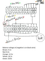
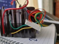
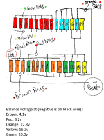
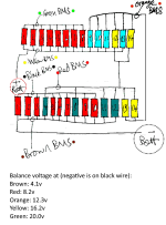
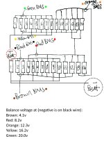
I do, however, have an issue. My battery is 24v (28 cells - see circuit diagram below). Most 24v BMS' I've found online seem to be 7s configuration (which tend to have 8 balance wires). Mine though only has 6 balance wires. Although I don't think its a 5s configuration. Mainly because I can't find anything online which is 5s and 24v. To be honest I can't quite figure out what configuration my battery is so any help is greatly appreciated.

IMG20230412124604.jpg
IMG20230412130438.jpg

Once I know that I can buy a new BMS. The cells are pretty nicely packaged up so I'd rather not change the configuration if possible.

Finally I plugged the battery into the bike. It promptly caused the BMS to trip the battery out*. So I unplugged everything on the bike. Put the battery back on and begun to plug stuff back in. Starting with the speed controller. Which caused the battery to trip out again. So no great shocks but it looks like I need to replace that too. Again its quite a cheap item so no great loss. Strangely this is exactly what happened with my other ebike. I think the previous owner jet washed it. I replaced BMS and speed controller and it was fine.

* So the BMS is clearly doing something but I suspect the charging issue is down to the BMS so I think it needs replacing anyway.

Thanks all.

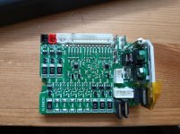
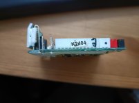
Some more images of the BMS as below:
IMG20230412130402.jpgIMG20230412130414.jpgIMG20230412130419.jpg
 
I do, however, have an issue. My battery is 24v (28 cells - see circuit diagram below). Most 24v BMS' I've found online seem to be 7s configuration (which tend to have 8 balance wires). Mine though only has 6 balance wires. Although I don't think its a 5s configuration. Mainly because I can't find anything online which is 5s and 24v. To be honest I can't quite figure out what configuration my battery is so any help is greatly appreciated
I added some color to your image to make it more clear, but the cell interconnects as drawn don't make sense. If they are actually wired this way, then the pack was built wrong, or was built of a mishmash of cells of varying capacities/capabilities, so they had to parallel more cells for some groups to get the correct capacity/etc. Is the battery on the other bike built the same way?

The way the drawing shows it is built is:
red-8p
blue-4p
yellow-4p
green-4p
orange-8p
which is not normal.

It should have all groups being 4p in this case, because the 8p groups, if all cells are matched, each have 4 "useless" cells in them, because the capacity in those cells can never be used since the other groups in series with them would be empty by the time that capacity comes into play.

It is built as a 5s pack, which is only 21v fully charged (assuming 4.2v full per cell). This would usually be called an "18v" pack (the average voltage, around 3.7v/cell). This is verified by your measurements in the drawing.

Note that built this way, it should be used only with a charger that can output 21v max. If it is used with a "24v" charger (29.4v actual), the cells can be damaged (with the potential for fire at any time from then on into the future) if the BMS fails to stop charge current for any reason.

Also note that built this way, it will not operate a 24v controller correctly; it will only work for a small part of its actual capacity, and then the controller will shut off the motor to protect what it thinks is an empty 24v pack.

It *should* be built as a 7s pack, or 29.4v full, which makes a "24v" pack, average.

For the BMS, to replace it you'll have to find one that is a 7s (or higher) that can be operated at 5s.

Or rebuild the pack to what it should have been, cutting the two 8p sections to make four 4p, then changing the series connections so there are then 7 x 4p sections in series, and use a 7s BMS (with a properly wired balance connector).


IMG20230412124604a.png


Strangely this is exactly what happened with my other ebike. I think the previous owner jet washed it. I replaced BMS and speed controller and it was fine.
If the same problem happened with the other bike, then the same solution is probably going to be required. :(

Note that generally regardless of what it might say, none of this stuff is really waterproof, at best water resistant. Jet washing (pressure washing) it is likely to get at least moisture inside various parts, and then over time it will do what water usually does in electrical systems.

So any part of the bike that was jet washed probably has moisture or actual water intrusion, and potentially has damage from this (even if it does not show yet). It affects electrical stuff more easily than mechanical stuff, but it can also damage bearings, etc. that would stay "sealed" against normal environmental water intrusion (rain, etc), but can't prevent intrusion by the pressurized jet of water.

Something to keep in mind and look out for over time.
 

Attachments

  • IMG20230412124604a.png
    IMG20230412124604a.png
    54.3 KB · Views: 1
Just to reiterate I think the charge port to BMS connection is fine. The battery is fairly simple in design. Cells, BMS and some wires. Nothing else (no fuses or diodes - at least none that aren't on the BMS). Actually it has a power level indicator up by the on/off switch.
Note that there are diodes on the BMS; at least ten parts marked "Dxxx" where xxx is a number. Whether they are in series with the charge port, preventing voltage from appearing on the charge port, you'd have to trace the circuitry on the BMS, between the charge port and the most negative main cell connection (usually marked as B-) to find out. The most likely one for this case would be the largest one inside a white outline in the green area of the board, marked D21, because of it's size.

I can't tell what the part is at the far lower left, in the white area, but some SMT fuses look like that, so it could be a fuse, or another diode; it is in the right physical area of the board for a charge fuse or diode.

BTW, the BMS itself is a 7s unit, it has 7 balance resistors (the larger 101 marked parts), even if your cells are not built in the correct configuration to be used this way.
 
I added some color to your image to make it more clear, but the cell interconnects as drawn don't make sense. If they are actually wired this way, then the pack was built wrong, or was built of a mishmash of cells of varying capacities/capabilities, so they had to parallel more cells for some groups to get the correct capacity/etc. Is the battery on the other bike built the same way?

The way the drawing shows it is built is:
red-8p
blue-4p
yellow-4p
green-4p
orange-8p
which is not normal.

It should have all groups being 4p in this case, because the 8p groups, if all cells are matched, each have 4 "useless" cells in them, because the capacity in those cells can never be used since the other groups in series with them would be empty by the time that capacity comes into play.

It is built as a 5s pack, which is only 21v fully charged (assuming 4.2v full per cell). This would usually be called an "18v" pack (the average voltage, around 3.7v/cell). This is verified by your measurements in the drawing.

Note that built this way, it should be used only with a charger that can output 21v max. If it is used with a "24v" charger (29.4v actual), the cells can be damaged (with the potential for fire at any time from then on into the future) if the BMS fails to stop charge current for any reason.

Also note that built this way, it will not operate a 24v controller correctly; it will only work for a small part of its actual capacity, and then the controller will shut off the motor to protect what it thinks is an empty 24v pack.

It *should* be built as a 7s pack, or 29.4v full, which makes a "24v" pack, average.

For the BMS, to replace it you'll have to find one that is a 7s (or higher) that can be operated at 5s.

Or rebuild the pack to what it should have been, cutting the two 8p sections to make four 4p, then changing the series connections so there are then 7 x 4p sections in series, and use a 7s BMS (with a properly wired balance connector).


View attachment 332526


If the same problem happened with the other bike, then the same solution is probably going to be required. :(

Note that generally regardless of what it might say, none of this stuff is really waterproof, at best water resistant. Jet washing (pressure washing) it is likely to get at least moisture inside various parts, and then over time it will do what water usually does in electrical systems.

So any part of the bike that was jet washed probably has moisture or actual water intrusion, and potentially has damage from this (even if it does not show yet). It affects electrical stuff more easily than mechanical stuff, but it can also damage bearings, etc. that would stay "sealed" against normal environmental water intrusion (rain, etc), but can't prevent intrusion by the pressurized jet of water.

Something to keep in mind and look out for over time.
Hi, thanks so much.

You're absolutely correct. My diagram was wrong. I'd missed a couple of key bits. Sorry.

I've had a quick redraw of the circuit as below. I 'think' everything is in 4p now.

Its late and I've spent all day looking after the kids so quite possible I've made further mistakes but so far it all seems correct. I'll have another look in the morning.

Thanks again.

IMG20230412124604.jpg
 
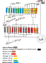
Ok, based on your new drawing, which I've colorized to make groups clear, you do have a 7s 4p pack. Your BMS must be internally wired to not require the main + and - on the balance leads, so in reality your groups are on the wires you have drawn in there, and so your measurements need to be done like this:

Battery negative (gray in drawing)
Balance connector Black
Balance connector Brown
Balance connector Red
Balance connector Orange
Balance connector Yellow
Balance connector Green
Battery positive (blue in drawing)

That gives you 7 cell groupings, 8 total wires
. IMG20230412124604.png
 
Ok, based on your new drawing, which I've colorized to make groups clear, you do have a 7s 4p pack. Your BMS must be internally wired to not require the main + and - on the balance leads, so in reality your groups are on the wires you have drawn in there, and so your measurements need to be done like this:

Battery negative (gray in drawing)
Balance connector Black
Balance connector Brown
Balance connector Red
Balance connector Orange
Balance connector Yellow
Balance connector Green
Battery positive (blue in drawing)

That gives you 7 cell groupings, 8 total wires
. View attachment 332571
Brilliant. Thanks again.

I'll order the BMS and get it wired up. Probably worth making sure I can get the battery properly working before I get a new speed controller etc....
 
Back
Top