Help with proper 10s6p battery pack welding/tab config

dis360

1 µW
Joined
Mar 8, 2023
Messages
2
Location
North carolina
I have a scooter that came with a 10s3p 6Ah (2 rows of 15 cells) battery pack 2023-08-15 23_16_25-Scooter - Google Drive.png, I am building an upgraded 10s6p 18Ah (4 rows of 15 cells) battery pack. Due to the cells being 4 rows of 15 (desired outer pack dimensions) a simple welding configuration like 6 rows of 10 can't be used.

My ultimate request is for help to determine/confirm the proper welding/tab configuration to get a 10s6p 36v battery pack.

The closest I've come to finding an example of a 10s6p (4 rows of 15 cells) battery pack is in the Segway Ninebox G30 Max. I grabbed a couple of screenshots from others attempting to resolve battery issues and noted their welding/tab configuration.
2023-08-15 23_17_16-Scooter - Google Drive.png 2023-08-15 23_17_08-Scooter - Google Drive.png2023-08-15 23_16_48-Scooter - Google Drive.png

Other 10s6p 36v packs
2023-08-15 23_17_00-Scooter - Google Drive.png

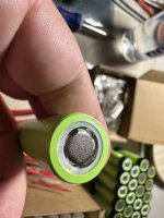
I have replicated the above battery configuration and proposed the following tab configuration. This picture is the pack I'm assembling and it's facing the camera on side 2 in my diagram below.
2023-08-15 23_17_25-Scooter - Google Drive.png 2023-08-15 23_15_59-Scooter - Google Drive.png

Thanks
 
It will work electrically, and if you require positive and negative on the same end, that's how you need to do it,

Another consideration is current flow thru the nickle strips. The series current has to flow thru two horizontal strips for eight of the groups. Look at what your strips can handle and what you plan to flow thru the battery, You'll probably have to stack extra strips to get the needed capacity. It takes experience plus a good welder to put down aux strips that won't pull off.

Also, I don't recall seeing cells with all that visible metal around the positive terminal. Did someone rewrap them, and not use the white PVC o-ring around the cap? Call me super cautious, but even though you have cell holders, I would add those paper o-rings around the top of each cell. Probably one on each side of the cell holder, if you;re missing the white ring.
Even the no-name commercial batteries I have bought use the paper rings.

When you spot weld, you're going to miss the center on a few cells. When that happens, you don't want the weld hitting that exposed metal ring. There's a second PVC insulator between it and the cell casing, and you don't want to stress it.
 
That’s some stellar advice doc, thank you.

I hope my cells aren’t rewrapped, they were purchased new but maybe the picture didn’t do it justice. The insulator is there, it’s just translucent, looks like this.

IMG_4111.jpeg
IMG_4112.jpeg

With that is it still recommended to add further insulation? Doesn’t sound like a bad idea, especially on the negative side.

The tabs Im using are,
0.15mm-0.2mm x 8mm
IMG_4109.jpeg
IMG_4108.jpeg

I used a calculator to find a happy medium between amperage and resistance and came up with those tabs. I plan on using a 40amp max BMS but currently only have a single hub that will max out at about 16amps, I would like to later add a second hub for upwards of 32amps.

As far as adding additional tabs on a the sections flowing more current, is there a downside due to adding more resistance at those points?

I know it may be a lot to ask but where would I add the BMS 10 series wires to monitor each group. It’s the positive location at the start of each series?

Thanks
 

Attachments

  • IMG_4110.jpeg
    IMG_4110.jpeg
    1.1 MB · Views: 6
The DIY-industry accepted practice is to use additional paper rings for insulation on positive side.
And @docw009 is right about the current thing - check how much current is safe for the nickel strips you're planning to use (but if you're thinking about 20 amps draw then it should be ok with single layer)
And regarding the BMS wires, one wire goes between each section in series which means you need to solder a wire to every tab
 
Back
Top