Hemi eTorque motor adpatation

Joined
Jun 4, 2023
Messages
4
Location
South Florida
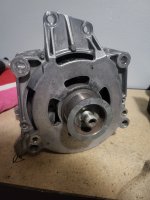
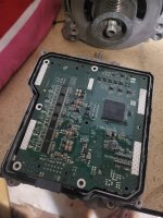
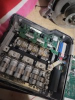
Hello everyone, I'm currently trying to adapt the 48v eTorque motor off a Ram 1500 for use on another vehicle. I've already read through this thread on the subject. Follwing where that thread left off I first looked into talking to the OEM controller with CAN. I found some technical documentation on the controller and the unfortunate reality is that in the OEM application the motor only drives the engine during a start stop event. This obviously wont serve my needs as I want to have precise torque and regen control.

I've also considered buying a controller and doing away with the OEM one altogether. Probably the easiest solution but the price has me looking for other options.

This brings me to the lebowski contoller. I've done a little bit of reading up on the forum but there's a lot of information and I'm not sure where to start. I'm basically looking for any and all guidance I can get. How much does building a lebowski controller typically cost? I'm not an electrical engineer or anything like that, so will trying to make one be way over my head? Is there somewhere you'd reccomend starting to get my feet wet? Any and all help would be greatly appreciated.

There's also some pictures of what I'm working with
 

Attachments

  • 20230618_080334.jpg
    20230618_080334.jpg
    1.6 MB · Views: 3
  • 20230618_080421.jpg
    20230618_080421.jpg
    1.8 MB · Views: 4
  • 20230618_080440.jpg
    20230618_080440.jpg
    1.6 MB · Views: 3
Building the Lebowski depends on your skills and what you price your time at, and whether you want to build the whole brain board yourself, or buy one from someone like KiwiFiat (which is what I did), and whether you want to design (or copy an existing design) and build your own power stage, or hijack that in either your OEM controller or some other controller.

There have been various OEM controllers' powerstages hacked to use the Lebowski brain instead of their originals, so following one of those builds' paths is a bit easier than completely going DIY on it, for those that are well-documented. Some are on various large-EV websites (some linked in my thread below), and at least a couple here on ES:

(mine, though I never got to the testing stage yet, project been on hold due to life/etc)
and Markexec's (in progress)

I don't recall the cost of parts on mine, I might have posted those in my thread, but my guess is a couple hundred dollars per brain / powerstage set, not including bits and bobs I already had from various other projects and test equipment/tools bought for the purpose (but useful for many others).

Note that the Lebowski brain needs standard UVW hall sensors to operate, AFAICR, so if you don't have those in your motor you'll have to install them either on the motor or on something attached to the output shaft with a new magnet ring matching that in the motor, so the brain can track rotor position and send the right phase signals. (it might operate sensorless once it gets going but I'm pretty sure it needs the halls to startup).
 
I'd suggest replying to JK130 in his thread about using this motor & controller, see if he made any progress with it to avoid doubling efforts.

You mentioned you're not an EE, but we don't know what your skillsets are. Your skills might complement his and might be able to help move the project forward. If you don't think you can help, you will have to wait or inspire others (bounty) on doing all the work.

Figuring out how to control the CAN bus would mean you're locked in to how the factory / Magnetti Marelli programmed the controller to work. There will be some window where you can drive it differently but it's hard to know how much wiggle room is there until it's hacked. Hard to say if it's just getting torque request info from the ecu or also working with the transmission computer info. These communications can be faked to run the eTorque setup but you'd need to build a bridge (electrical, communications, and code) to whatever you have as an ICE engine and figure out from info on that side of things and battery info when it regens, outputs drive power, and how much when. It's not a small or simple project. Of course this is a bit easier and safer on a dyno. Without a dyno will be tricky and can get dangerous quickly.

When I do design work, I consider every added piece of the puzzle to double the work required to get things working properly. It's very easy to underestimate the time and skills required. If you have the time and enough of the different skills it could be a great way to learn. It can very easily go the way of wasted time and frustration too.
 
Thanks for your replies, after reading up on this some more it does seem like something I can do. What I think I'm gonna try is to either use kiwifiat's board or make my own controller and use the powerstage that came with the motor.

If I'm not mistaken I will need to connect to the current sensing circuit and figure out how to properly drive the gates.

I've identified the current sensing ICs (in red) and found a data sheet on them. I'm not sure however what kind of gates these are, looks like they were custom made for this controller. So the next step is to get some more info on those, if anyone could help shed light it'd be much appreciated.

20230620_120520.jpg

I believe everything else I'd need to get this work is
1. Hall sensor on the motor
2. Throttle pedal signal
3. Brake pedal signal
4. 48v supply

If there's anything I'm missing/any pitfalls I should know about please let me know. I will likely make a dedicated thread for this build once I've made some actual progress.
 
Thanks for your replies, after reading up on this some more it does seem like something I can do. What I think I'm gonna try is to either use kiwifiat's board or make my own controller and use the powerstage that came with the motor.
By "make your own controller", do you mean build an existing design and use the existing software? That's fairly easy to do, as long as the design is versatile enough to adapt to the specific powerstage you end up using.

If instead you mean design one yourself and write the software for it...that's a big project and usually gets pretty expensive in powerstage parts as you learn how to drive them. (that can happen even with an existing design optimized for a different kind of powerstage than what you use). If you go this way, there are a few multiyear design threads for various types of controllers you may want to read first.


If I'm not mistaken I will need to connect to the current sensing circuit and figure out how to properly drive the gates.
I've identified the current sensing ICs (in red) and found a data sheet on them.

If you can't use the current sensors taht are built in there, you could get compatible ones that read current from a wire passing thru them, and install them over your phase cables.


I'm not sure however what kind of gates these are, looks like they were custom made for this controller. So the next step is to get some more info on those, if anyone could help shed light it'd be much appreciated.
Do you mean IGBT's (they're probably not FETs). The gate drivers are probably much smaller, probably on the back side of the current sensor board or another separate board not visible in the image.


I believe everything else I'd need to get this work is
1. Hall sensor on the motor
2. Throttle pedal signal
3. Brake pedal signal
4. 48v supply
If that powerstage was designed for 48v, then yes. (some are designed for much higher voltage, and usually IGBTs are used on 100V+ systems because they're less efficient than FETs but better at high voltages, so usually only used at those higher voltages. ) You can use the powerstage at lower voltages, as long as either it's onboard power supply to run it's gate drivers and current sensors, etc., will operate correctly at that lower voltage..it's just less efficient than a FET powerstage, if it's IGBTs. (If it's onboard PS (DC-DC) can't operate at a lower voltage, you would have to cut it out of the circuit electrically, and wire in a different one that can, and that can supply the necessary voltage(s) at sufficient current). But you generally can't use it at a higher voltage than it was designed for.

Whatever traction supply you use, it must be able to handle the worst-case stall current of the system, for the longest time this can ever happen worst-case.

You'll also need whatever power supply your brain board uses (IIRC the Lebowski version I got some time back from KiwiFiat uses 12v input, so I have a small DC-DC to run it off the traction battery).

The hall sensors need to be the UVW type of setup, meaning as used on 3-phase motors where there is one hall for each phase for timing/position. If there are no sensors installed, you can install them, but you have to determine the correct placement within the stator to get the right timing for the phases (there are threads about adding halls to various BLDC motors). Or use an external set with a magnet ring on the output shaft, etc.
 
By "make your own controller", do you mean build an existing design and use the existing software? That's fairly easy to do, as long as the design is versatile enough to adapt to the specific powerstage you end up using.
I guess I could have been clearer, I'm either going to build a lebowski controller based on the DIY or buy kiwifiats board.


Do you mean IGBT's (they're probably not FETs). The gate drivers are probably much smaller, probably on the back side of the current sensor board or another separate board not visible in the image.
I'm not sure how to identify the difference without any part numbers or a spec sheet. I was able to identify the gate drivers on a separate board and I have a spec sheet for them. Will I need to reuse those? I thought the lebowski controller had its own drivers.

The powerstage I'm using came with the motor so it is designed for 48v
Whatever traction supply you use, it must be able to handle the worst-case stall current of the system, for the longest time this can ever happen worst-case.
Traction supply is the battery right? Sorry I'm new to a lot of these terms. And I don't know the stall current. There's not a lot of.published info about this motor. I was going to spec a battery that could handle the maximum output of the motor continously, add a healthy safety factor on top of that, and then fuse my B+ cable. I figured that would be good enough.
 
I guess I could have been clearer, I'm either going to build a lebowski controller based on the DIY or buy kiwifiats board.
Might be worth looking around at
openinverter.org wiki & the forums there. They have some can man in the middle and the zombieverter boards to control oe setups.
The powerstage I'm using came with the motor so it is designed for 48v
The dc-dc, fets, and capacitors may have a higher max voltage than required for 48v. You could maybe run it at a higher voltage if the components can handle it. It's a nice to know before you start.

Traction supply is the battery right? Sorry I'm new to a lot of these terms. And I don't know the stall current. There's not a lot of.published info about this motor. I was going to spec a battery that could handle the maximum output of the motor continously, add a healthy safety factor on top of that, and then fuse my B+ cable. I figured that would be good enough.
You could use the hybrid (48v) truck battery specs as a starting point.
 
I'm not sure how to identify the difference without any part numbers or a spec sheet. I was able to identify the gate drivers on a separate board and I have a spec sheet for them. Will I need to reuse those? I thought the lebowski controller had its own drivers.
I asked if it was the IGBT you were referring to because you called them gates, but gates (gate drivers, anyway) don't usually have all those conductors to them; only power handling devices usually do. Typically they use IGBTs in these things, because of the high voltages they usually use.

The powerstage I'm using came with the motor so it is designed for 48v
Ah. Most of the EV stuff I've seen starts above 100v, some of them a few hundred volts.


Traction supply is the battery right?
Yes--many systems have multiple power sources, so traction battery is for the motor, and other supplies might be called aux(iliary) or lighting or LVPS (low voltage power supply), etc., depending on what it's used for.

Sorry I'm new to a lot of these terms. And I don't know the stall current. There's not a lot of.published info about this motor. I was going to spec a battery that could handle the maximum output of the motor continously, add a healthy safety factor on top of that, and then fuse my B+ cable. I figured that would be good enough.
That's probably good enough...but***. Do you know what the rating for fuses or breakers that fed that controller were on the vehicle it came from? That would help you know what the controller itself is capable of.

***keep in mind fuses don't blow at the current they're rated for. Check with the fuse manufacturer's data sheet for exaclty how the one you're going to use works, but generally that is the rating they are guaranteed to continuously handle up to. Beyond that, then it depends on how much over the limit the current is for how long it will take the fuse to blow. For instance, If it's only a few amps over, it might take minutes to hours to blow (or never, if there is a lot of airflow on the fuse keeping it from melting). If it's a thousand amps over, it might blow in a millisecond or less.
 
Life unfortunately got in the way of this project for a little bit. There's some great advice here though.
Might be worth looking around at
openinverter.org wiki & the forums there. They have some can man in the middle and the zombieverter boards to control oe setup
The openinverter board is very interesting, it seems like it would be compatible with the resolver already on the motor which is a nice bonus.
You could use the hybrid (48v) truck battery specs as a starting point.
This seems so obvious now I'm kicking myself for not thinking of it myself. Definitely going to be looking into this too.
 
Back
Top