okashira said:
Can I ask some random Q's...
How are you driving those massive IGBT's? It looks like the 333J is way too weak to handle those huge IGBT's?
Boost stage If you look at the sch and PCB files you will see it
Why did you choose those IGBT's? They seem old...?
I got 7 of them for $200 so that's a start....
How you looked at the 3 phase infineon igbt modules? :-DD Nice packages.
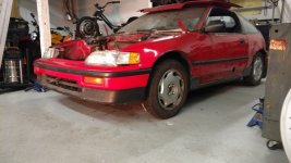
Non on the modules can do the power I want. I don't want some granny car I will to make something fast!
Cool project!
Thanks.
I have a lot of things on the go this is one of them. I have a new design that will use TO264 igbts and should be easier to assemble and more power dense.
All In time. I will be running more tests tomorrow. Last night I shorted the high side and tested the desat at 227v and tomorrow I will test at 460v.
With 227v the current climbed to over 1300 amps in just 6.8 uS

But the desat did shut it down and save it....

")