Hobby King LVC/HVC/PARALLEL V3.0 Design Thread (open mic)

methods said:
wOoT ->
Latest board run came in and they work. Good F'ing thing too because I sank ever last dollar I had into a run of 1,200 boards :twisted:
Parts (optos) are back-ordered, but we will be releasing a few little things like the 4S, 5S, and 6S parallel only boards in a day or two.
They wont be cheap but they will make some peoples builds easier - especially motorcycle guys.

-methods

How do these ones differ again? I'm happy to order my 5S boards with nothing soldered on them except a 6 pin male JST (preferably 90 degrees ;))

I just ordered another 30 battery PCBs but for 4P. I didn't sink my last dollar into it but it was money I would have spent keeping the Blackbird on the road for another year :lol:.
 
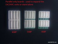
I just made up some parallel boards
A board with 8 JST connectors on it
done in 6S, 5S, and 4S versions

IMG_20120504_094016.jpg

Used to ease the pain of paralleling up packs
Really they are for the motorcycle guys.

IMG_20120504_093951.jpg

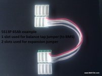
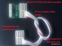
My new LVC/HVC/Parallel boards have only 6 JST slots
That means they could go up to 5P, or 25Ah
They then use the final slot to expand out to another board - giving them an additional 6P

IMG_20120504_093927.jpg

-methods

jonescg said:
How do these ones differ again? I'm happy to order my 5S boards with nothing soldered on them except a 6 pin male JST (preferably 90 degrees ;))

I just ordered another 30 battery PCBs but for 4P. I didn't sink my last dollar into it but it was money I would have spent keeping the Blackbird on the road for another year :lol:.
 
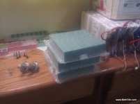
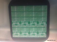
We have an assload of PCB's

IMG_20120502_104519.jpg

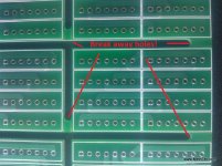
Each panel has 6 of the LVC/HVC/Parallel board and 6 parallel only boards.
We break the panel in the middle and stencil the LVC/HVC -> then hand populate the parallel only

IMG_20120502_104536.jpg


Added some holes this time - they break up nice and easy

IMG_20120502_104607.jpg

We added some new features.
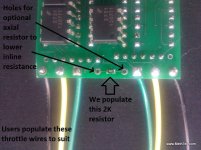
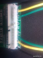
We now include pads on the board for going inline with the throttle. We populate a 2K resistor that should work for most controllers. We also added a spot where users could solder in a standard Radio Shack axial resistor if they need to lower the inline resistance. Some controllers (like Lyen) have too low of input resistance on the throttle requiring much lower inline resistance. Any resistor here will be paralleled with the existing - so a 1K or a 800ohm would do the trick.

IMG_20120504_094622.jpg
View attachment 2

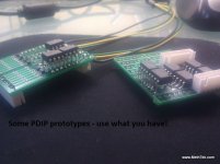
Here are two prototypes - one on the old board and one on the new.
IMG_20120504_094653.jpg

-methods
 
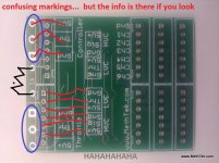
All of the information needed is now on the PCB
It is not clear at first... but once you look at it for a while it makes sense

Out at the edge we have the connections to the throttle and controller
3 pins each
So 3 names

Inside we have the daisy chain jumpers
6 signals each
Users dont really need to tap into these - markings are just for DIY mods/tinkering

IMG_20120502_104411.jpg
IMG_20120504_094612.jpg


So really all you guys are interested in are the throttle and controller connections
Maybe the add on resistor
Ignore all the rest

We now marked the cells from 1-6
Cell one is the lowest and connected to ground
Cell six is the highest voltage


We are going to make these up in 6S, 5S, and 4S
Here is a 4S example for those pesky hard packs that everyone loves

View attachment 1


-methods
 
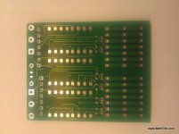
Here is the bottom of the board where all the parts go
2 parts per channel: one detector and one opto
Total of 12 parts for a 6S board, 10 parts for a 5S board, or 8 parts for a 4S board

IMG_20120502_104449.jpg

We will be waiting on parts for a while so no populated pics
Still have not even ordered the solder stencil

Plan is to populate all the surface mount and bake in the oven
Then flip over and populate the JST connectors

Users will then populate the throttle connections

-methods
 
Note that I was able to tent all the via's...
This is important!!!

Electrolysis is the great enemy
It is super easy to accidentally put two via's close together that have a large voltage potential
Say line 7 which is at 25V and line 1 which is at 0V
One drop of water and you will eat up an 8mil trace in to time

So... by tenting the via's we have that much more insurance against liquid issues.
We will still conformal coat - but the less exposed metal the better.

Tenting also allows the silk screen to be easier to read across the PCB


-methods
 
Back
Top