Is it a hall throttle, or potentiometer?
If it's a hall, it requires three wires, and won't work on that controller--the controller is not designed for this kind of input and you'd have to change the throttle to the kind it expects. (it could blow up the hall sensor, or cause the motor to not run or to run full out always or always run a little even when no throttle movement is made, etc).
If it's a potentiometer, it only requires two, though most controllers use all three.
Set your multimeter to 20 k ohms, and put the red lead on the first wire of the throttle unit. Move the black wire to each other wire, and note down the readings on each. Move the red to the next wire, then the black wire on the next two wires, noting down each reading. Repeat for the next one. This tests for resistance between each one. If it's a 3-wire potentiometer, one pair of wires will read around 5kohm, 10kohm or so. Another pair will read close to zero ohms, or actually zero, or nearly the same as the first pair. That pair, when you move the throttle, will change it's reading. When you find the pair that changes from zero to full resistance (whatever the ohms is), that's the signal and ground.
A pair that includes the voltmeter probably wont' read anything (OL on the meter, or whatever it shows for no connection).
Which one is ground depends on how it's wired with the voltmeter. If there were three wires for the pot, the ground is common with the meter. If theres' only two wires for the pot, the meter is probably the other pair of wires, and it doesn't matter which is ground on the throttle wires. But which one is ground for the meter does matter; it may blow up the meter if you hook it up backwards. You'll probably have to test using the original controller (even if it doesn't work to drive the motor) to find out which is which, by measuring voltages on it's connector pins using the battery negative as the black meter lead connection point.
Also, some controllers with only two wires do not actually have a throttle input, only a switch input (even if it's called throttle). (like those on very low-powered "kick scooters"--these don't even use FETs but rather relays inside the controller).
In any case, I've only seen two wire throttles on brushed controllers, so if your motor is not brushed, my guess is this controller isn't compatible with it, though I've not yet seen a brushed controller with a display, either.
For us to do more than guess about that and other things you'd need to post complete details about the system you're fixing up or building, along with links to any of the items you've bought to replace things with.
kmxtornado said:
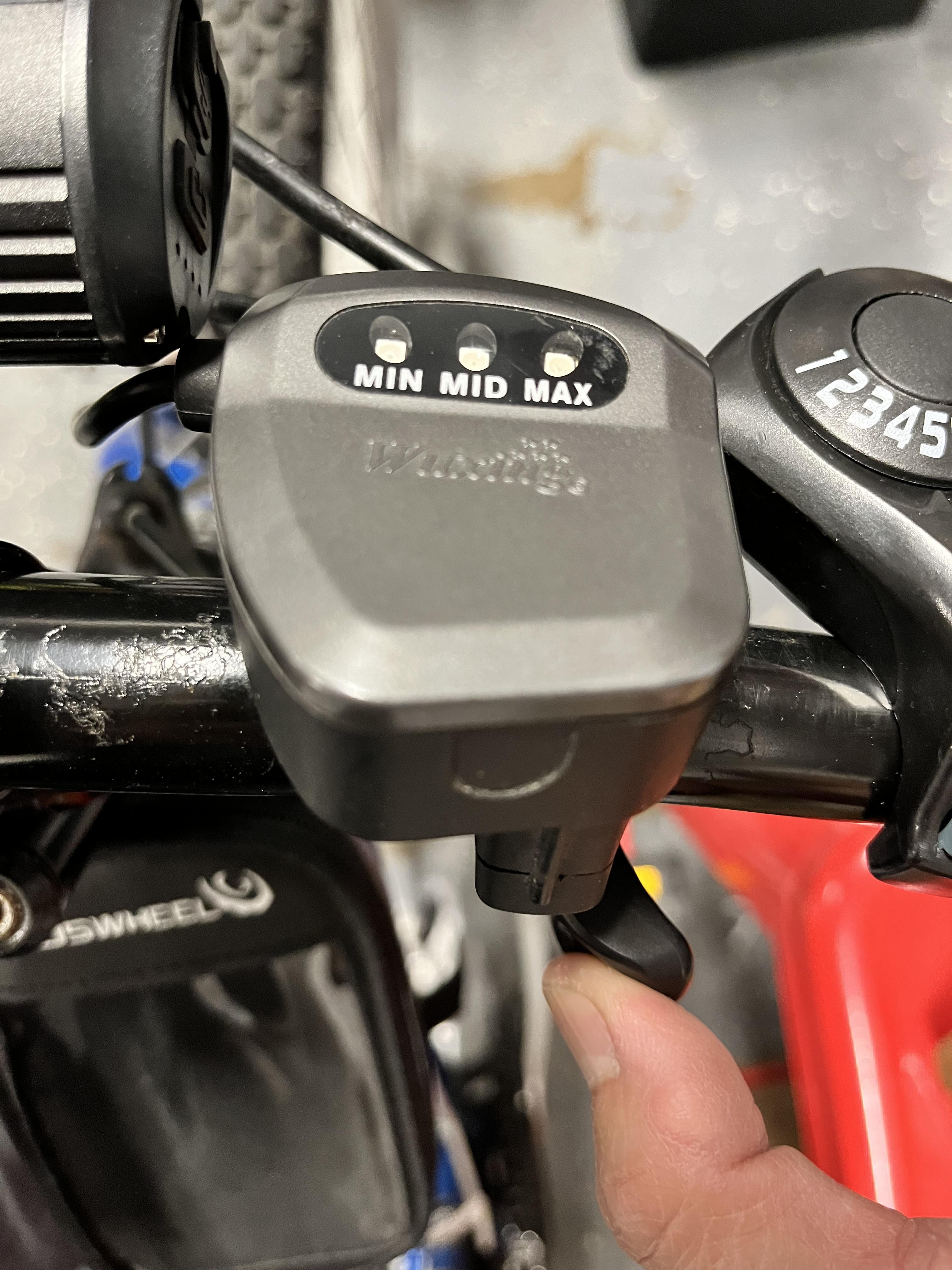
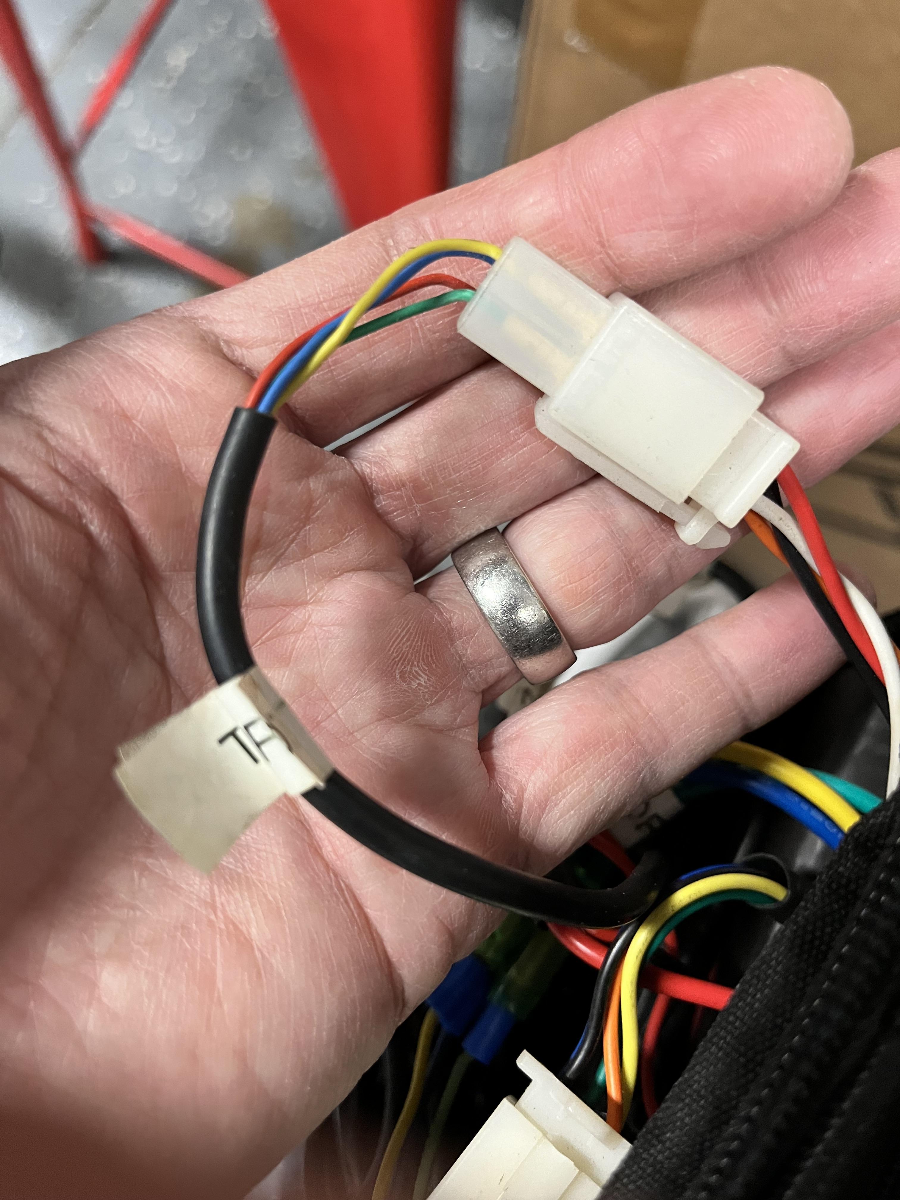
Hi, thanks in advance. I have this old school thumb throttle with integrated voltage meter from 11 years ago. I'm replacing my controller, but the throttle wires on the new controller only has 2 wires. How do I make the connections? My guess is that two of the 4 wires are for power to light up the voltage display and the other two wires are for the throttle itself. If so, which wires are which?