Still throttle wiring problems

medusa569

100 W
Joined
Sep 17, 2010
Messages
161
Location
Washington DC
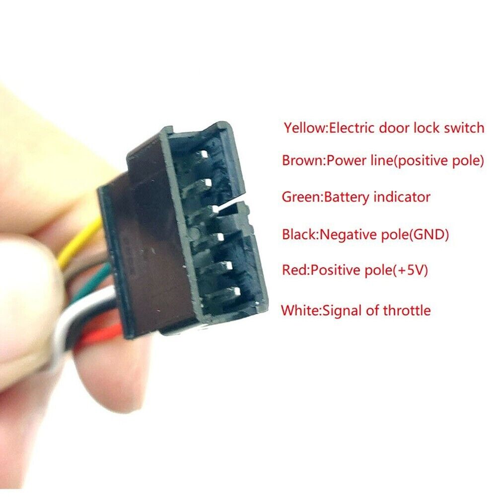
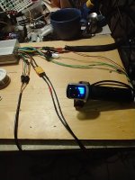
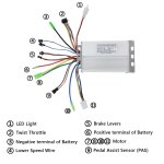
OK since I couldn't figure out the 6 wire throttle I bought a 4wire throttle ( 3 + yellow power wire for LED) . Is the yellow for throttle high voltage or low? I see by some videos it says to connect straight to battery but I can't figure out how to do that unless i connect the throttle yellow wire and chain it in the back of the controller power large postive. Does anyone have a pic of how they connected their throttle yellow? I‌ assume the throttle will work without the display? My remaining consideration would be for the left over 3 wires the controller throttle connection had. Additionally the diagram for my controller is somewhat vague. The 4 "motor" wires are not clear.
 

Attachments

  • Voilamart 36 volt controller 500w.jpg
    Voilamart 36 volt controller 500w.jpg
    214.9 KB · Views: 39
Last edited:
You need the display to power it up. If you remove it, you;ll have to rewire the display connector too.

The display gets 48V from the controller. probably the red wire. When the display is turned on, it sends 48V back to the controller to power up the circuits, probably on the blue wire. If you don't wish to blow up your controller, test this with your multimeter. Plug the display in. Make sure red lead is 48V and blue is 0v until the display powers up.

Now you should know how to wire up the throttle. It has a wire diagram too?


voila.jpg
 
You need the display to power it up. If you remove it, you;ll have to rewire the display connector too.

The display gets 48V from the controller. probably the red wire. When the display is turned on, it sends 48V back to the controller to power up the circuits, probably on the blue wire. If you don't wish to blow up your controller, test this with your multimeter. Plug the display in. Make sure red lead is 48V and blue is 0v until the display powers up.

Now you should know how to wire up the throttle. It has a wire diagram too?


View attachment 341349

First my controller does not have the same wiring as your diagram. There is no electric lock nor a blue wire on the throttle. Throttle has red,black,green and yellow. Secondly my controller is rated 36/48 volt. Thirdly do you mean that the yellow should be connected to the large red power wire on the controller that will plug in to the battery? Somehow I will need to connect it to the back of the xt60 as opposed to directly the battery as some videos say. I don't see how that is possible unless I make a third anderson connector grouped with the other pos and neg power wires aqnd all three would connect and disconnect together. I‌ also wonder how the thin yellow wire (‌the same size as the 3 throttle wires will be carrying 36/48 volts.
 
Your first controller picture shows the 6 pin display connector. You may not have a lock, but the controller in that picture isn't going to power up if the display is unplugged.
Well I‌tried again today first 3 wires standard for throttle connected and the final yellow throttle wire I attached to the burgundy/brown wire on controller throttle connector. Still no luck... It seems as if something needs to be done with the remaining 2 controller throttle wires.....Do I‌ connect them together or what? If I had more info about the controller that would help but I'm out of luck about that.
 
Last edited:
I‌ assume the throttle will work without the display?
This from your opening statement may have thrown a few off, including me. By display, in this instance you are referring to the voltage display on your new throttle. Are you not?

That and with the understanding that the controller wiring diagram in your original post is correct for what you have…

Doing a bit of research I found this throttle that looks like it would go to your controller.
Take a look at the throttle’s pictures and you will find a wiring pin out with descriptions.

1 Pair 6 Wire E-Bike Throttle 36V Electric Scooter Grip Handlebar LED Display | eBay

First a word of caution. Manufactures do not always use the same wire colors! Be wary, and verify before wiring and power up.

With the throttle disconnected, at the controller wiring I suggest you verify the high voltage power line (BROWN wire) and be sure to keep it away from your low voltage halls sensor wires!

Hall Sensor Wires:
RED= 5vdc +
WHITE= Sensor signal wire and
Black= Battery negative. (Use this connected to your meter’s BLACK lead when testing for voltages.)

As the good Doc mentioned previously, you will need to jumper the power wire to the “Electric Door Lock Switch” YELLOW wire.
I believe that the GREEN wire will now have full battery power, And the controller’s electronics will be powered, providing 5vdc supply on the RED wire. Check for both those voltages now.

If every thing checks out so far you can go ahead and wire up the hall sensor wires and see if it works. Then if all is well…
you can decide if you want to use the 6 wire throttle you have, or the 4.

If you do not totally understand my descriptions, or are unsure of the wiring. Ask before wiring and trying. There are other methods of verification.

Good luck!
T.C.

P.S. To clarify the 4 wire motor wires… 3 are the phases, the last refers to the motor’s hall sensor connector.
 
Hey tc: So when you say jump the power wire its as I described...basically joing tother the red postive power and the yell throtte wire together than then add on connector for battery connection? I don't know what green wire you are referring to. I‌am NOT uing the 6 wire throttle as it is a twist gripe (dangerous). I‌use thumb throttles initially trying my preexisting 3 wire throttle...it didn't power up. I then bought the 4 wire throttle and with yellow wire disconnected it didn't power up. Since the have no diagram on the controller electronics we have no idea as it hw it NEEDS to be wired in order to work. The ony thing I do know is that it is marked as a dual mode controller so I've been doing sensorless connections, just throttle and phase wires. I‌ guess I'll just have to wire theyellow up to my power red goign to battery and see if that does the trick. I will never buy a kit again just based on price. I'm gonna make sure i get diagrams and/or a support phone #.
 
Yes the first pic IS what I have. Let you know how it goes.

Fine, in the throttle posting that I found for it, the wiring pin-out and colors were given.
s-l1600.jpg


Sorry for the size...

This picture may help explain my earlier post and required wiring.

To be specific...
In order for the controller's electronics to be powered up. The BROWN and YELLOW wires at this connector need to be jumped, or tied together. Then, the GREEN wire at this connector should have full voltage to it, which can be connected to your throttle's YELLOW positive voltage display wire.
Note: Connecting the RED battery power to your YELLOW throttle wire alone will NOT energize the controller.

Please RE-read my connection and voltage tests in my post above, and the sequence of connecting. Verify that the correct voltage is where and when it is supposed to be first. Being careful not to let the high voltage wiring come in contact with the throttle's low voltage hall sensor wiring.
 
Fine, in the throttle posting that I found for it, the wiring pin-out and colors were given.


Sorry for the size...
If you click on the image after inserting it, you get blue handles at the corners to resize it.
 
Hey Tommy! I'm finally checking in again as I laid out my components on a work board, changed some connectors etc. I finally found the supplied twist throttle to see if something was missing would recitify itself with the 6 wired throttle. Well...nothing changed. No power showing on throttle nor in the motor. It dawned on me that it might demand the hall sensors to be connected as well even though I assumed it would run sensorless since they offered a dual mode controller. But as I go to connect the wires for that I notice that the controller has 6 wires for the halls and the motor has 5 wires for the halls! WTH? I don't know if my assumption was right and I don't recall reading any other posts whether anyone else has run it sensorless it would seem I'm at an impass. I‌ will reread and try you suggestions again after I give myself a breather this afternoon. Hopefully I'm wrong and there is some other problem that does not allow it to power up. I‌ connected just the controller to battery to see if any voltage was detected on any connector so I checked to measure the 5v on the throttle wires and I got nothing. Again I assumed that any power would show once connected to a power source.
 
Last edited:
Followup...sucessfully connected 5 wire twist throttle so at least I know that I‌ was able to achieve display and battery voltage. However the motor showed no signs of life. It may have something to do with the white wire that has no mate. Onother site identified white hall sensor wire as a temp gauge but I don't know if that's true. I thought I'd read somewhere that the white was the signal wire for the motor but with no white wire on the motor I'm stuck again. Did anyone else has a 6 controller to 5 motor halls?? THere is alkso a tiny red item on the throttle display. I can't make it out.‌What's it for?
 

Attachments

  • VoilaMart  36v kit.jpg
    VoilaMart 36v kit.jpg
    342.6 KB · Views: 6
Last edited:
When trying the 6 wire original throttle, did you turn the switch on?

Check out this video…


I’d recommend using the throttle with the voltage display also. Much better than a bar type battery charge indication.
 
Well after 5 months it's finally running !!! Hallefrickinlujah. Apparently for this kit 36/48 volt 500W The whole problem is the wiring for the throtlle and the controller setup. I‌ used the included twist throttle which I may alter or switch out in the future but for now I just hope there is some longevity to this kit. The wires (hall and phase) are awfully thin 23/14. I‌ predict burns in the future but let's see. Apparently for this motor you can run it senseorless, You don't need the pas installed in order to work as electric bike. All the wires are same color to color match. Tomorrow my maiden ride.
 
Last edited:
Back
Top