Darren2018
100 W
- Joined
- Aug 18, 2018
- Messages
- 223
I would like to make a 100V mosfet switch and I would ideally like to make it as simple as possible, could someone with some experience help me please :?
amberwolf said:More details on specific usage will be needed to do a design.
Some things we'd need to know (there may be more depending on those):
--What specifically is it intended to switch? (what is the complete system on either side of it?)
--How much current must it be able to handle continuously?
--What is the actual system voltage; what are the max voltages ever present under any conditions?
--Will it be sealed into something, or will it be allowed airflow?
--Does it need to block flow in both directions? Or just one?
--Does the current need to flow both directions? Or just one?
(corollary: If used on a battery to a controller/etc, does it need to handle regen?)
--What will power the switch? (same source as it switches, or separate)
Darren2018 said:I would like to switch an isolated DC-DC which steps down the 92.4V max battery to 13.8V as this powers my uLight/Nucular. The step down converter makes a huge spark when it is at zero volts. I need it to switch the battery side so it completely disconnects it from the battery so as to not draw any current or power the display. The circuit powers the LED front, rear and USB which add up to around 70W so I do not expect to ever pull more than 2A continuous from the battery. I would like it to be powered from the main battery with only one switch if possible.
amberwolf said:More details on specific usage will be needed to do a design.
Some things we'd need to know (there may be more depending on those):
--What specifically is it intended to switch? (what is the complete system on either side of it?)
--How much current must it be able to handle continuously?
--What is the actual system voltage; what are the max voltages ever present under any conditions?
--Will it be sealed into something, or will it be allowed airflow?
--Does it need to block flow in both directions? Or just one?
--Does the current need to flow both directions? Or just one?
(corollary: If used on a battery to a controller/etc, does it need to handle regen?)
--What will power the switch? (same source as it switches, or separate)
amberwolf said:Since you don't need current flow except in the outbound direction, that simplifies operation and design.
Do you need a separate switch for the lighting, or would you like it to just come on as soon as the main battery is switched on? If you need a separate switch, there is a much simpler-to-build solution than a mosfet switch.
Is the spark at 0v actually in the converter? Or is it in a connector you are plugging in from it's input to the main battery?
If the former, there is a defect in the converter (bad connection, etc) that needs to be repaired.
If the latter, using a precharge resistor on it (just like on a controller) would fix this much more simply than a mosfet switch. The precharge resistor can be on a momentary N.O. pushbutton, paralleled with the actual lighting switch that powers the DC-DC from the battery. Press the precharge switch for a few seconds, then turn the switch on; no spark, and no connector issues.
If pressing a button for precharge is more than desired, a relay can be wired up to autoconnect and disconnect the precharge as power from the battery at the main power switch is turned on and off.
Darren2018 said:I would like to switch an isolated DC-DC which steps down the 92.4V max battery to 13.8V as this powers my uLight/Nucular. The step down converter makes a huge spark when it is at zero volts. I need it to switch the battery side so it completely disconnects it from the battery so as to not draw any current or power the display. The circuit powers the LED front, rear and USB which add up to around 70W so I do not expect to ever pull more than 2A continuous from the battery. I would like it to be powered from the main battery with only one switch if possible.
amberwolf said:More details on specific usage will be needed to do a design.
Some things we'd need to know (there may be more depending on those):
--What specifically is it intended to switch? (what is the complete system on either side of it?)
--How much current must it be able to handle continuously?
--What is the actual system voltage; what are the max voltages ever present under any conditions?
--Will it be sealed into something, or will it be allowed airflow?
--Does it need to block flow in both directions? Or just one?
--Does the current need to flow both directions? Or just one?
(corollary: If used on a battery to a controller/etc, does it need to handle regen?)
--What will power the switch? (same source as it switches, or separate)
Darren2018 said:I have thought about connecting it to a pre charge circuit but I don't want too many physical switches and a loop key is not really durable enough as I think the lights turn on right away. I would prefer to stick to a mosfet due to its simplicity and ruggedness but I just don't know how to do it properly.
![IDcct1[1].gif](https://endless-sphere.com/sphere/data/attachments/179/179665-5b296ffd9fc841f20d70823b855b83b7.jpg "IDcct1[1].gif")
![IDiode143[1].jpg](https://endless-sphere.com/sphere/data/attachments/179/179666-a872d253dfc17d6448ec4a15bbebdfb9.jpg "IDiode143[1].jpg")
![IDBolt149[1].jpg](https://endless-sphere.com/sphere/data/attachments/179/179667-797614bca294ed38c2c6799425e70f88.jpg "IDBolt149[1].jpg")
OK. Suggestion:Darren2018 said:I would like to switch an isolated DC-DC which steps down the 92.4V max battery to 13.8V as this powers my uLight/Nucular. The step down converter makes a huge spark when it is at zero volts. I need it to switch the battery side so it completely disconnects it from the battery so as to not draw any current or power the display. The circuit powers the LED front, rear and USB which add up to around 70W so I do not expect to ever pull more than 2A continuous from the battery. I would like it to be powered from the main battery with only one switch if possible.
amberwolf said:FWIW, the precharge resistor (even with a relay to automate it) is simpler than a fet switch, and much more rugged (it can't be killed by voltage spikes or overcurrent/overheat/etc, and if it does fail it doesn't fail shorted like a fet does so it wouldn't leave your dc-dc turned on with no way to turn it off other than disconnecting it).
But I'll see what I can find for simple schematics for a fet switch to do what you're after.
It's possible that Tiberius' Ideal Diode board, or Methods' antispark FET Switch designs will work or be adaptable.
Darren2018 said:I have thought about connecting it to a pre charge circuit but I don't want too many physical switches and a loop key is not really durable enough as I think the lights turn on right away. I would prefer to stick to a mosfet due to its simplicity and ruggedness but I just don't know how to do it properly.
JackFlorey said:OK. Suggestion:Darren2018 said:I would like to switch an isolated DC-DC which steps down the 92.4V max battery to 13.8V as this powers my uLight/Nucular. The step down converter makes a huge spark when it is at zero volts. I need it to switch the battery side so it completely disconnects it from the battery so as to not draw any current or power the display. The circuit powers the LED front, rear and USB which add up to around 70W so I do not expect to ever pull more than 2A continuous from the battery. I would like it to be powered from the main battery with only one switch if possible.
MOSFET: Infineon IPP075N15N3GXKSA1
MOSFET driver: TLP591B
Drive it with a 1K resistor from a 12V signal. If you want to drive it from 92 volts then use an 8.2K resistor.

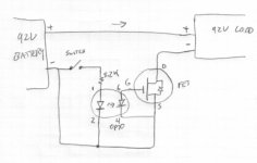
Sure try this:Darren2018 said:Please could you show me how to set this up? I might be able to figure it out myself but I don't want to break anything else
JackFlorey said:Sure try this:Darren2018 said:Please could you show me how to set this up? I might be able to figure it out myself but I don't want to break anything else
. Maybe I could use your design for my other projects which do not require the positive to be switched. Do you know how to make the same thing but with a P channel mosfet? Also do I need to put a diode across the isolated DC-DC? 
1) You can put that on either side. The opto FET driver is isolated so it can go on the + or the - side. N vs P channel doesn't matter since the gate is not referenced to the drive voltage.Darren2018 said:I think I might need a P channel because I need the positive +90V wire to be switched
No. You will blow the gate of that MOSFET. No MOSFET is going to withstand -92 volts on its gate.Darren2018 said:Would this be ok
JackFlorey said:1) You can put that on either side. The opto FET driver is isolated so it can go on the + or the - side. N vs P channel doesn't matter since the gate is not referenced to the drive voltage.Darren2018 said:I think I might need a P channel because I need the positive +90V wire to be switched
2) Why do you need to switch the + lead instead of the - lead anyway? They both do exactly the same thing.
3) You should not need a diode.
4) If your diagram is accurate none of this will work. If it's a transformer you need an inverter first.

Darren2018 said:I thought the isolation in most common DC-DC converters was done with a coil, diodes, mosfet and an opto isolator, this is why I asked for help :lol: .
Ah. Well, all you really need in a diagram for this purpose is a box labelled "DC-DC" with a + and a - terminal on the input for battery voltage, and a + and a - terminal on the output for whatever that voltage will be.When I googled isolated DC-DC schematic most of the designs used what looked like a coil so I just copied it.
If the converter is getting hot when switched via the negative, and not when switched via the positive, something is wrong with the way it or it's load is wired. So we should troubleshoot that before continuing, so you don't end up with other problems down the line.The reason I want to switch the positive is because I initially tried to switch it using the BMS which caused the converter to get hot.
Specs on the page sayI found an Aliexpress item which showed the switch being on the positive so I just assumed that the gnd must be shared as it would explain why it got hot even though it was disconnected from the battery gnd.
This is the converter that I have:https://www.aliexpress.com/item/1005003071825636.html?spm=a2g0o.order_list.0.0.793a1802pBz0ay
).Ah, OK. Usually I just use a box to make it clear that it's an assembly, not a transformer.Darren2018 said:When I googled isolated DC-DC schematic most of the designs used what looked like a coil so I just copied it.
You can do either one.The reason I want to switch the positive is because I initially tried to switch it using the BMS which caused the converter to get hot. I found an Aliexpress item which showed the switch being on the positive so I just assumed that the gnd must be shared as it would explain why it got hot even though it was disconnected from the battery gnd.
amberwolf said:Why do you need to switch the positive wire? Unless you have something wired from the output of the DC-DC back to the input side, like using your frame as ground for the lights, then the positive and negative are identical and it makes no difference which one you switch; it's all one big circuit loop and breaking it anywhere is the same.
Regarding your diagram (copied below), you didn't mention it is a transformer. For a transformer you can't use DC input, you have to drive it from AC, so you will need an inverter on the output of your battery to drive the transformer the same frequency and voltage as it was originally designed to output. No diode, though.
Then you will need a rectifier and capacitors on the output to convert it to the DC voltage for your lights.
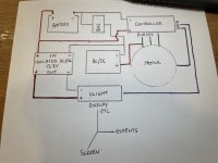
Darren2018 said:This is how I have connected it?
I think it got hot when I opened the charge or discharge mosfets, I can't remember which ones. It made an arcing noise and was around 50C in just a few seconds.
You have your charger connected to one of the phase connections? That can work but you need VERY specific software (and a way to lock the rotor on a BLDC) to get it to work.Darren2018 said:This is how I have connected it?
amberwolf said:Darren2018 said:This is how I have connected it?
Please note that you show the controller negative always connected to the battery negative, and not to the BMS negative. Is that correct?
If so, then there is a possible current path when you siwtch the BMS discharge FETs off.
(this current path would also still exist if you use a switch of any kind in the ground wire from the BMS to the DC-DC).
Does your system require you to bypass the BMS's ability to protect the battery from overcurrent and overdischarge for a specific reason? If not, I recommend not connecting the controller negative directly to the battery, and instead running it thru the BMS discharge FETs, both for those issues and others as analyzed below.
Some analysis below, it might be repetitive as I thought of different things as I was editing.
What wires are in the cable marked "data", coming from the Ulight, going to the controller?
If it contains a ground wire, and the Ulight does not have isolation between the data ground and it's power source ground (which most things don't) then that is a ground path feeding the output of the DC-DC, removing the isolation it should have from the battery side, effectively connecting the two together, whenever the DC-DC's negative input is connected to the battery.
The problem in your case of removing power via the BMS is that if (probably) there is a ground in the data lines from Ulight to controller, you have connected just the output of the DC-DC, not it's input, to the battery negative, permanently. This also makes the DC-DC's battery output ground *more negative* than the input ground (because the BMS drops a little voltage across it's FETs), which if it is completely isolated internally wouldn't make a difference to it's operation.
But what exactly happens inside the DC-DC under those conditions we'd need the (unavailable) actual internal schematic of that specific DC-DC to figure out. Most likely, nothing unusual under any normal condition (including removing the ground via the BMS FETs).
Mostly, it just means that the DC-DC is not isolated anymore, if it was built isolated, as far as DC-DC operation should be concerned, assumign it's properly designed and not defective or damaged.
Are there other devices connectted to the Ulight that also connect to system ground, at any point? If so, please add them to to the diagram, exactly as wired. They may also make a difference to current paths available in one condition vs the other.
I think it got hot when I opened the charge or discharge mosfets, I can't remember which ones. It made an arcing noise and was around 50C in just a few seconds.
If the DC-DC got hot when *not* powered, and the wiring is as noted on your diagram, there is something wrong with it internally; design, or defect or damage, because it should be completely isolated and that should not happen--no current should flow in any way from the output to the input...but it appears to be doing so via the battery ground to the controller to the data wires to the ulight to the output negative of the DC-DC, and then thru internal parts back to the battery positive (the only possible current path).
If the DC-DC actually made an arcing noise inside, from actual arcing, under *any* within-spec conditions at all, ever, it is poorly designed (unsafe) and/or defective or damaged. I would recommend a different one that doesn't do that.
Notes below regarding devices themselves, if wired correctly, meaning all power controlled by the BMS, which is not the case for your diagram; your BMS controls only the charger output and the DC-DC input grounds; it doesn't control any other device's grounds, as those all are fed via any grounds in the data lines, bypassing the BMS and feeding them by the presumably tiny wires in the data lines (probably unintentionally, but there nonetheless).
They don't apply to your system because of the direct ground connection from battery to controller, preventing the BMS from cutting the ground connection (so it cant' actually protect your battery from any overcurrent or overdischarge).
If opening the charge FETs on a BMS that has a device wired just to the discharge FETs (assuming separate ports) causes any change of state to a that device, there's either something wrong with how the wiring was actually done vs how you intended it to be done (which connections were made), or something wrong with the BMS itself. Potentially something seriously wrong with the device itself.
Opening the discharge FETs on a BMS that has a device (with isolated input and output, and or properly designed internally) wired to them, should do nothing other than remove power from it.
![IMG_0196[1].JPG](/sphere/data/attachments/179/179710-ddfb93a10ac1732b6400d1f17c84f451.jpg)