how to make a proportional / variable regen ebrake brake lever

Mahe said:
That is the most elegant solution I encounter so far! I'd love to reproduce that work but it does not seem straightforward to realize. I'd have a few questions to that end:
- could you provide a seller link or specifications for the hall sensor + magnet you used? I suppose they are various kinds.
- can you explain the role of the screw again please? I understand it is convenient to adjust the distance between hall sensor and magnet and calibrate it accordingly. Do I understand correctly that using an iron screw, the screw itself becomes the magnet sensed by the hall sensor?
- what range of distances between sensor and magnet are we talking about actually? (or between sensor and screw tip, if that's what it comes down to)
- how instrumental is your specific brake model ? Would such an approach work fine with some standard, middle range, say my simple Shimano brake levers? (I'm thinking of the screw, the cavity for the hall sensor a'nd the free range before triggering mechanical brakes). Probably any setup where hall sensor and magnet are brought closer together by braking would do it, right? Like roughly tape/glue the hall sensor on the fixed brake body and magnet on the brake lever, near the point of contact? But sure a clean setup is important. Often there is some play in the brake lever with respect to the fixed part. Could that contaminate the signal to the point of making the sensor useless for braking? (again the distance/sensitivity question)

Many thanks in advance for any hint you may provide!

Mahé

i used A1324LUA-T linear hall sensor. You can order those example in Digikey, Farnel etc. Look places using Google.
Role of that screw is to be magnetic tip, which i can easily adjust (how far / close it is to hall sensor). And round magnet is easy to glue top of screw. Also in my brake levers (Hope Tech 3) there was place for that screw. I just replaced original red screw to some screw that is ferro / iron material and can magnetized.
 
Great, thanks, I'll give it a try.

I assume you are still happy with your solution (i.e. stable, no drift over time or need to recalibrate often ?)
 
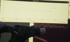
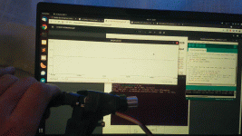
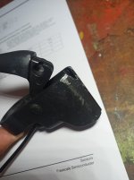
Just as a follow-up, I made last year a try with the components suggested by @Nixunen (hall sensor A1324LUA-T and -- I think it was -- radial magnet 9027). Here just as a proof of concept, I taped the sensor on the fixed part of my brake lever (some lower or mid-range shimano brake lever) and the magnet on moving part (the lever), then plugged it onto an Arduino board to monitor its response (see below for connection).

View attachment 1


The response is excellent, but I never proceeded to actual implementation on my bike. Remaining challenges to implementation:

1. Figure out the connection to my Cycle Analyst (CAv3) (EDIT: or just connect to dedicated regen brake plug of my controller)
2. Have a mechanically sound setup

For 1, the challenge is that CAv3 only take a digital e-brake signal, and variable regen occurs through the throttle when braking is active. Therefore, Grin suggested (a) to open the CAv3 and splice in the e-brake wire with the throttle input, or (b) to connect the e-brake wire directly to the Phaserunner controller (since I happen to use a Phaserunner). The latter may be easier (see below) but requires running another cable to the controller, and cut open the controller cable to access the relevant wires (the e-brake regen signal is hidden and spliced in with the throttle).

For (a), Sensor pins to connect (1) supply voltage 5V, (2) ground and (3) output voltage, here 5V when released (full contact) and 2.5V when fully braking (no contact between magnet and sensor). According to CAv3 connection diagram (https://ebikes.ca/product-info/grin-products/cycle-analyst-3.html or PDF manual), the supply voltage for the e-brake plug is the same (5V), and there seem to be enough options in the CA to interpret the correct cutoff (I believe here "active low" logic and something like 4.9V as cutoff -- I didn't try that yet), but then I'm not sure how to map the 5V->2.5V e-brake output signal onto the expected throttle range of 1V->4V, and how not to interfer with normal throttle working (EDIT: it seems to me that using the normal throttle will trigger e-brake !!). In any case, it seems hard to avoid building some circuit, and that does not appeal me.

So I suppose (b) will be much easier, and the reduced hassle well worth pulling an additional cable to the controller.

Here comes in the second challenge: is any of that worth the hassle with a poorly taped sensor as shown in the pics? (which will move and be affected by rain). @Nixunen had a brake model apparently more suited for a clean mount. Maybe I should find one (any recommandation for an easy-to-modify, unexpensive model ?).

So in summary, the difficulties discouraged me and I have not done any more work on that for a year. Now I am thinking, I'll probably try with a second throttle dedicated for regen (give up on the intuitive brake lever for now), and run the cable to the phaserunner. Unless someone here has a better suggestion?

Thanks.
 

Attachments

  • Screenshot from 2022-08-26 12-43-50.png
    Screenshot from 2022-08-26 12-43-50.png
    424.8 KB · Views: 304
  • freno-regenerativo.gif
    freno-regenerativo.gif
    7 MB · Views: 304
I'm a huge proponent of regen braking. My current setup includes a Grin all-axle motor and phaserunner combo, and I average between 10 and 20% regen per ride, and this is relatively flat MN terrain. I only touch the brake levers for emergency stops or as a 'parking brake' (I ride a recumbent). I understand the 'intuitive' argument for doing regen with the brake lever but personally now favor the entire regen (stop & go) experience being centered on the throttle. I've acquired a Tesla within the last year and driving this car has only added to my conviction that a "one pedal" operation, based on the throttle, is the best way to operate a vehicle. The ideal control for my purposes is a bi-directional throttle, with a detent for the neutral (0.8-1.0V) zone. Finding a well-engineered device at a reasonable price still eludes me. My current (interim) solution is a DIY device on each side of the handlebars consisting of a SPST momentary switch coupled with a generic (Grin) thumb throttle, with all devices wired in parallel to the CA3. The Phaserunner is programmed for a moderate level of regen when the momentary button is pushed, and the thumb throttle turns into a variable regen device while the button is depressed. This isn't ideal from a UI point of view, but otherwise works remarkably well.
 
Thanks much for your prompt replies.

stancecoke said:
?! There are very cheap commercial brake levers with linear output available today. No need to tinker....

Thanks for the recommandation. It's hard to see what the technical specs for that brake lever are (input and output voltages) but I 'll look that up. I also forgot to mention: it's important that the lever actually pulls my V-Brake cable. The main reason for the latter, is that I have to limit the strength of the regen braking to avoid overheating (the GMAC overheats very quickly on regen in a mountainous environment, with 800W input currents...), and I find using different mechanisms for regen and emergency braking simply dangerous (there are often > 10% slopes with pot-holes).

@rowbiker, I need a natural brake lever for safety reasons, or more accurately, to be able to ride a little more aggressively. I can tell after one year use of brake lever + throttle regen that having it "working" is not enough in certain ride conditions. That's because at higher speed or on more difficult terrain I need to have both hands firmly on handle grips, fingers ready on the levers. Having one slightly activating the e-brake, and the other playing with the throttle, is really not that great sometimes, and I have either to be very slow or give up on regen. Also I'd like to be able to lend my bike to someone else more easily (now I just keep silence on regen, that's also OK).
 
Here another idea how to modify an existing, digital e-brake lever into a linear output:
https://www.youtube.com/watch?v=ZcjtN6g1BzI

(@stancecoke or anyone else: any hint where to purchase linear output lever for electric V-brake most welcome...)
 
?! The one linked above (for a M365 Scooter originally) should work with a V-brake without problems, see this detailed photo:
IMG_20220826_211528_865.jpg

This was my DIY version I built before the commercial ones were available :wink:

[youtube]gE2KvwUhD1w[/youtube]

regards
stancecoke
 
Ok, I'll give it a try then. Many thanks for the advice.

PS: looks like a working DIY build !
 
Are there any solutions available for hydraulic brake levers? I've got a nice functioning Shimano brake lever+caliper system on my cargo bike I'd like to modify with a Grin system for proportional regen braking
 
Specifically which "Grin system" are you going to use, and specifically how do you want your braking to work?

The *runner controllers have a direct variable braking input, and settings to handle the voltage range it's expecting (easiest to implement), or the CA can be used with the throttle input controlling this, engaged by a switch in the brake lever (the complicated workaround method covered by my initial posts in this thread).

If you're using the CA to do the braking, then unless you're looking to do an input switching of the CA like I'm doing in this thread, your throttle will be doing the braking control after the lever engages the brake. If your levers don't have switches on them, there are a few ways of adding one to the caliper or the lever.

If you want the brake lever to vary the braking, then you'll have to either install a pressure transducer into your brake line(s), add whatever is needed to power it, and built something (arduino, etc) that can translate that voltage range into a throttle voltage range, or install something external at the lever or caliper that can vary the voltage (hall sensor with magnet, cable mount to pull a throttle, potentiometer, etc).

There have been some threads/posts about using transducers; I dont' have a direct link to them handy.
 
(@stancecoke or anyone else: any hint where to purchase linear output lever for electric V-brake most welcome...)
Grin Tech ebikes.ca now sells one:
 
Specifically which "Grin system" are you going to use, and specifically how do you want your braking to work?

The *runner controllers have a direct variable braking input, and settings to handle the voltage range it's expecting (easiest to implement), or the CA can be used with the throttle input controlling this, engaged by a switch in the brake lever (the complicated workaround method covered by my initial posts in this thread).

If you're using the CA to do the braking, then unless you're looking to do an input switching of the CA like I'm doing in this thread, your throttle will be doing the braking control after the lever engages the brake. If your levers don't have switches on them, there are a few ways of adding one to the caliper or the lever.

If you want the brake lever to vary the braking, then you'll have to either install a pressure transducer into your brake line(s), add whatever is needed to power it, and built something (arduino, etc) that can translate that voltage range into a throttle voltage range, or install something external at the lever or caliper that can vary the voltage (hall sensor with magnet, cable mount to pull a throttle, potentiometer, etc).

There have been some threads/posts about using transducers; I dont' have a direct link to them handy.
From what I've read the grin controllers (cycle analyst and the "superH") can take analog/variable input to have adjustable regenerative braking. They sell cable actuated levers (linked above) for this but not hydraulic levers. I've inquired direct with them but haven't heard back. I don't plan on using a throttle for my Grin All Axle V3 w/ torque sensor build.
 
Back
Top