How to repair faulty WL-086-01 LiFePo4 BMS?

Joost

1 W
Joined
Mar 31, 2014
Messages
54
Hello,

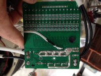
After i finish repairing my battery pack i hooked up my BMS. Now i have the problem the BMS will not workshop After a hour.

My question is how to mesure/repair a BMS??? What are the steps too begin?

Please i used the search function but cannt find a older topic.

Kind regards,

Joost
 
that is because nobody fixes them. no way to know what you are talking about since there are no pictures and no information of the problem.

i have repaired more than a dozen. really very easy to diagnose and repair if you have any skills.
 
Hello,

I have some trouble to upload photos so I try too explain.

I have a 16s LiFepo4 pack with a WL-086-01 ver. 1.3 bms.
Now it the problem it will not charge anymore after a little spark.
Wen I connect the pack to my scooter and charger I masure 5V on both legs of the charger FETs. The charger is set too 58.3V and the pack is now 54V.

Too charge I need the trick off connection the charger FET legs...
On the backside there is a 106 resistor between the legs of the charger FET and the discharged FETs.

What is the best way to start?
 

Attachments

  • image.jpg
    image.jpg
    94.4 KB · Views: 1,026
  • image.jpg
    image.jpg
    77.3 KB · Views: 1,026
  • image.jpg
    image.jpg
    68.6 KB · Views: 1,026
  • image.jpg
    image.jpg
    50.4 KB · Views: 1,026
  • image.jpg
    image.jpg
    56 KB · Views: 1,026
there was a spark because the BMS touched one of the terminals of the battery?

can you point out where the BMS touched the battery?

it looks like one of the mosfets has been unsoldered from the pcb, and the heat sink has been removed already. was there something wrong with the heat sink or is that where the battery terminal shorted?

the 2 mosfets in the upper left corner are the charging mosfets. tied in parallel. R02 is the drain down resistor on the gate that bleeds the charge off the gate when it is turned off. 106 means 10x10^6 or 10Mohms which is normal. you want to measure the voltage across that resistor, which is voltage between the gate leg and source leg in order to know if the charging mosfet is turned on.

but the output mosfets also have to be turned on so measure the gate source voltage on them also.

the mosfet legs are gate, drain, source from left to right. measure between gate and source legs. you only need to measure one since they are all in parallel. you have to have the pack assembled with all the sense wires connected to measure.
 
I think I make it!!!
After mesure I found out that one G4EK was defect. Now it seems to work again. How can I adjustment the amps and cc/cv?
For now I let it charge too 3,55 with a total off 56,8V and it need to trickle charge.

Can you explain how to do this?

Thank you for your time

---------

Strange now it charge but not bleeding! One cell reach 4,04V...
 
how do you know the G4 comparator is defective? usually when they fail the shunt transistor is stuck turned on so that channel will drain down through the shunt resistor if you leave it connected to the battery through the sense wire.

you should put the battery on the charger and measure the voltage across the shunt resistor on each channel. if you battery is still uncharged none of the shunt transistors should be turned on so there should be no voltage across the shunt resistor for any channel.

so measure those first, it your G4 is shorted it can be replaced. i have some parts on used BMSs here too if you need them. not easy to replace but it can be done.
 
What is the shunt resistor? The resistor above the big bleeding resistor?
 
the shunt resistors are called the balancing shunt resistors and are the big blue 5 W resistors with the red black black or 20ohm value.

if the comparator is shorted it will turn on the shunt transistor. but usually it is the shunt transistor which is damaged and not the comparator.

so if you measure a voltage across the shunt resistor, that means there is current flowing through the resistor. there should not be current flowing through the resistor if the cell is below the balance voltage which is 3.60V so if you measure a voltage below 3.60V on the shunt resistor that means that the channel is shorted and it will drain down the cell to 0V if you leave the sense wires connected. but connect them now so you can measure the voltages on each one but on the one you suspect for sure. this is always the first thing to do when a BMS is causing one cell to drain down to lower voltages than the other channels.

wait wait. i had not looked at your picture to verify because you said G4 which is usually a smd comparator used to control the shunt transistor as well as the HVC and LVC signal lines but you have a different setup for the balance using a resistor divider bridge which is that collection of tiny resistors next to the legs of the shunt transistors.

all of those npn transistors standing on end next to the shunt resistors are the shunt transistors and are not the normal pchannel mosfets used in most BMS. read the part number off of the transistor and google it. i may have some here too. but verify there is voltage across the shunt resistor first.
 
Thanks for your input.

There is no voltage reading between then resistor legs, only between the bottom leg of the left one and the bottom leg the next resistor. On one cell resistor I read 4,04V.....
Not one resistor is working....


The code on the transistor is SS8550 D331
Btw I measure 20 ohms on the resistors so I think they are T


_ (R1B 225)
_ (R1C 475)
_ (R1D 106)
_ (R2B empty)
_ (R2C empty)
_ (R2D(106))
Transistor SS8550
|
|
Resistor
 
4.04V between cells is overcharged for lifepo4. so your BMS is not broken, it has turned off because one cell has passed the HVC level of 3.90V.

did not realize this was the case. can you verify that your voltmeter is accurate somehow? then measure the cell voltages?

measure on the BMS where the shunt resistor is soldered to the pcb next to the sense wire plug. put one probe (black) on the first one and the second probe (red) on the next resistor leg and do that for each cell all the way up and list the cell voltages here. use the 20V DC scale.

but 4.04 is really high so i suspect your voltmeter could be misreading unless you were charging without the BMS for protection before this. in any case the voltage should be visible across the shunt resistor if it is that high.
 
I measure 4,04V wen I charge the pack well other chanals reads 3,3 3,56 3,68 3,78...

So my multi reader isn't defect

Some kind of reason it will not bleeding on all the chanals...

Is it possible to connect a new mini bms to my 16s 30Ah pack or will blow
Because of the Amp use by my scooter?
 
your battery should not be so far outa balance. the transistor on the channel that has the high voltage maybe burned open circuit so that could account for the lack of voltage across the shunt resistor.

there is just so little and incomplete data to work with. never learned from you where the BMS was shorted and how. no info on what the shunt transistor is and i am not sure you could test it but at this point it does seem like the transistor on that channel is burned open.

except i only have 3 voltage measurements and not the same range of value either. not sure what you mean about a mini BMS since that one seems fairly small already.
 
image.jpgAfter a night hanging the bms on the battery it now bleeding after connecti with the charger. The strange thing is that normally there is a spark wen I connect first the charger to the bms and then to the wall.

I measured every chanal and the same chanal reached 3,9V and the transistor stays cool.
The transistor is oke I measured it. What could be the problem that this chanal will not bleeding?
Could it be the G4EK?

Here is the measure


1 2 3
| | |
G4EK
| | |
4 5 6

1-2= 0,07V
1-3= 3,86V
2-3= 3,96V
1-4= 0,07V
1-5= 3,88V
3-6= 3,96V
5-6= 3,95V
 
Here the photos from the 'mini' bms.
It's a 15s I need to build to a 16s and as I can remember 30A max. Is it save too use on my scooter 1500W motor?
 

Attachments

  • image.jpg
    image.jpg
    69.6 KB · Views: 983
  • image.jpg
    image.jpg
    28.5 KB · Views: 983
  • image.jpg
    image.jpg
    27.7 KB · Views: 983
that is a 16S BMS but it is missing the bottom sense wire on the plug. that is not a big problem so if you wanna use this 'mini' BMS we can walk you through how to connect the very bottom wire.

i still think the original can be made to work, i just cannot get useful info from you.

i do have some of the 8550, they are available on ebay too but it is not clear that any of them are defective.
 
Hello again;)

I think I found the problem.
1) I've screwed the charger.... Not only the output voltage but also the cc/cv adjustment....... It blows the fuse on the charger.

2) becaus I had set the output voltage to 57,6V the bms wasn't actived....... I know I'm stupid
After adjust the output voltage on my last charge that work the bms is 'working'

Now the little problem is that two canals reach the max voltage so the bms sets him self off.
By connecting a car light to my multimeter I drain the canal so the bms can do his job. But... I need to do this many times.. Is there a way to solve this???

If I can make the bms work properly then in do not need the mini bms. But I'm not convinced


I'm thinking... Is it possible to connect the mini bms to do the balancing quicker??

Sorry for my poor English and stupid questions....
 
Another part replaced it from the first cell a '2A' after measure a backup bms I fingered out it was faulty.

Men what a pain in the ass electronics. It's a mess in my head and it was also before.
 
Back
Top