handbike_electric
1 mW
- Joined
- May 5, 2016
- Messages
- 12
In order to get a new handbike running properly with electric support - this means adjusting the motor behaviour to the lower human torque provided by arms instead of legs - there were a couple of things to be done. I wanted to have control over the motor, so a CA3 needed to be used instead the original electronics. Below, I am describing what I did. I hope this to be useful for others 
The basic idea of what we are planning to do can be found here in the second half of the post: https://endless-sphere.com/forums/v...sid=c403e1c1b247b75d7e18a5e6c2e715a3#p1182567.
Since the appropriate handbike is not yet finished, we did not yet bring our CA3 with the Sunstar motor onto the road. Nevertheless, on a bench the system proves to do what it is meant for.
General impression of the Sunstar S03+ : Pretty solid motor and drive train, nice bearings, appears to be a pretty good and solid thing. For details, see http://www.sunstaribike.com/e-bike-mid-motor-s03/s03-drive-unit/. BTW, their new Virtus motor can be adaped the same way like described below.
Ok, lets start. Motor needs to be opened, which is pretty easy by removing the screws.
Removing the cover on one side gives access to the last set of gears:
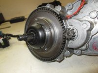
This side is not of further interest here.
(As a side mark, inside is the torque measuring sensor. Works by a spiral moving a magnet against a stationary magnet and pushed back by a spring. Change in magnetic field indicates the torque applyed by human and is being measures by three hall sensors. At the same time, thes three hall sensors can measure the cadence as well as the turning direction. This also explains the somehow soft feeling of the manual pedaling.)
(Second side mark: I heard of people in colder countries complaining about the sunstar motor switching off in cold temperatures just below freezing. On the PCB inside there is a NTC measuring the PCB temperature (not to be confused with the NTC I will discuss later to measure the motor temperature). It is expected, that the NTC above is responsible for temerature switch off assuming that the batteries are stored warm and only the bike is outside. When applying a 43kOhm resistor parallel to the given NTC, the switch off temperature is expected to be lowered from -5°C to -10°C. However, this has not been proven yet).
Removing the screws on the other side exposes the motor:
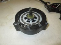
Shows the three phase connections and (barely visible) a window in the plastic frame allowing thermal contact to measure the temperature directly at the motor.
Note: When reassembling later make sure that the rotor is fully pressed into the stator before reinstalling the motor. If you fail to do so, the motor will most likely not spin freely but instead not run at all. Space is pretty tight and the magnets pull the rotor easily into a wrong position. There is a flat spring keeping the motor in place in operation just at the motor shaft, but it is not strong enough to force the rotor into correct position when mounting if not properly aligned before.
What remains, when the motor is removed, is the motor mount:
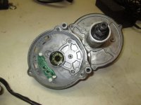
On the motor mount, you will find another PCB, measuring the motor temperature and the rotor location:
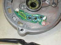
The red circle shows the 10kOhm NTC resistor. Since it already shares ground with the hall sensors, a one wire connection to the appropriate cable of the CA3 is enough. However, if you notice electromagnetic interference or wrong measurements, just seperate ground of hall and ground of temp sensor on PCB and use two independent ground wires to CA3. Sensor is covered with a white temperature conductive foam. This needs replacement, probably the best home solution here is to use the white insulating heat transfer paste which is generally used to mount cooling heat sinks on transistors. Thermal contact to motor surface as made through the opening in the plastic housing as described above.
Blue circles show the hall sensors needed for the controller for smooth operation.
Yellow circle shows the connector pins opening to a window on the other side for the cable.
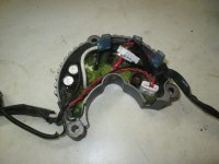
Here you can see the original power inverter, this is not needed any longer. Short cables are salvaged to create adapters for CA3 and the new power inverter, a C3620-NC from Grin.
Further removal of a cap opens the case to get access to the next gear:
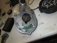
Here you see the plastic gear inside:
View attachment 5
Interestingly enough, the needle bearing is not just a bearing. It includes a freewheel functionality, see http://www.bearing-needle.com/7Ein-Weg-Rollenkupplung-Lager-HF-HFL-FC-FCB.htm. This allows to manually spin the pedals whithout automatically spinning the motor (e.g. if battery is dead).
It might be the case that this plastic gear needs replacement after a while, however replacement is pretty easy. And this is the only plastic part in the drive train. Please note to install in the correct orientation, when mounting upside down the motor can not provide any torque to the drive train.
This is the adapter cable for the hall sensors, made of the original connector cable to the hall sensor PCB. The other cable from the internal torque sensor is not needed for our handbike application.
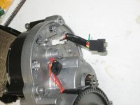
The hall adaptor cable was made using a crimping tool and proper JST plugs. I bought this one: http://www.ebike-solutions.com/de/s...en/crimpzange-fuer-jst-steckverbindungen.html.
And finally the adapter cable for the motor phases, also made salvaging the original cables to the original power inverter. Also used a serious Anderson crimp tool: http://www.ebike-solutions.com/de/s...nge-fuer-anderson-powerpoles-15a-30a-45a.html
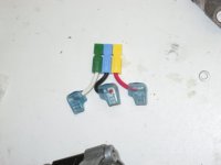
Here you can see, how the adapter cables are attached to the wires provided with the grin controller:
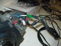
This shows the whole assembly of battery, controller and motor:
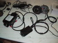
And finally everything works properly, CA3 showing motor temperature:
Last note: When running the motor sensorless on the bench without load I had thin probe wires with alligator clips. Most probably the connection was not stable, so induction caused over voltage causing my controller to die. Will tell in a seperate post how I fixed it again. So please be warned and use serious cables even for bench testing. The invest in a crimping tool is worth the effort.
The basic idea of what we are planning to do can be found here in the second half of the post: https://endless-sphere.com/forums/v...sid=c403e1c1b247b75d7e18a5e6c2e715a3#p1182567.
Since the appropriate handbike is not yet finished, we did not yet bring our CA3 with the Sunstar motor onto the road. Nevertheless, on a bench the system proves to do what it is meant for.
General impression of the Sunstar S03+ : Pretty solid motor and drive train, nice bearings, appears to be a pretty good and solid thing. For details, see http://www.sunstaribike.com/e-bike-mid-motor-s03/s03-drive-unit/. BTW, their new Virtus motor can be adaped the same way like described below.
Ok, lets start. Motor needs to be opened, which is pretty easy by removing the screws.
Removing the cover on one side gives access to the last set of gears:

This side is not of further interest here.
(As a side mark, inside is the torque measuring sensor. Works by a spiral moving a magnet against a stationary magnet and pushed back by a spring. Change in magnetic field indicates the torque applyed by human and is being measures by three hall sensors. At the same time, thes three hall sensors can measure the cadence as well as the turning direction. This also explains the somehow soft feeling of the manual pedaling.)
(Second side mark: I heard of people in colder countries complaining about the sunstar motor switching off in cold temperatures just below freezing. On the PCB inside there is a NTC measuring the PCB temperature (not to be confused with the NTC I will discuss later to measure the motor temperature). It is expected, that the NTC above is responsible for temerature switch off assuming that the batteries are stored warm and only the bike is outside. When applying a 43kOhm resistor parallel to the given NTC, the switch off temperature is expected to be lowered from -5°C to -10°C. However, this has not been proven yet).
Removing the screws on the other side exposes the motor:

Shows the three phase connections and (barely visible) a window in the plastic frame allowing thermal contact to measure the temperature directly at the motor.
Note: When reassembling later make sure that the rotor is fully pressed into the stator before reinstalling the motor. If you fail to do so, the motor will most likely not spin freely but instead not run at all. Space is pretty tight and the magnets pull the rotor easily into a wrong position. There is a flat spring keeping the motor in place in operation just at the motor shaft, but it is not strong enough to force the rotor into correct position when mounting if not properly aligned before.
What remains, when the motor is removed, is the motor mount:

On the motor mount, you will find another PCB, measuring the motor temperature and the rotor location:

The red circle shows the 10kOhm NTC resistor. Since it already shares ground with the hall sensors, a one wire connection to the appropriate cable of the CA3 is enough. However, if you notice electromagnetic interference or wrong measurements, just seperate ground of hall and ground of temp sensor on PCB and use two independent ground wires to CA3. Sensor is covered with a white temperature conductive foam. This needs replacement, probably the best home solution here is to use the white insulating heat transfer paste which is generally used to mount cooling heat sinks on transistors. Thermal contact to motor surface as made through the opening in the plastic housing as described above.
Blue circles show the hall sensors needed for the controller for smooth operation.
Yellow circle shows the connector pins opening to a window on the other side for the cable.
Here you can see the original power inverter, this is not needed any longer. Short cables are salvaged to create adapters for CA3 and the new power inverter, a C3620-NC from Grin.

Further removal of a cap opens the case to get access to the next gear:

Here you see the plastic gear inside:
View attachment 5
Interestingly enough, the needle bearing is not just a bearing. It includes a freewheel functionality, see http://www.bearing-needle.com/7Ein-Weg-Rollenkupplung-Lager-HF-HFL-FC-FCB.htm. This allows to manually spin the pedals whithout automatically spinning the motor (e.g. if battery is dead).
It might be the case that this plastic gear needs replacement after a while, however replacement is pretty easy. And this is the only plastic part in the drive train. Please note to install in the correct orientation, when mounting upside down the motor can not provide any torque to the drive train.
This is the adapter cable for the hall sensors, made of the original connector cable to the hall sensor PCB. The other cable from the internal torque sensor is not needed for our handbike application.

The hall adaptor cable was made using a crimping tool and proper JST plugs. I bought this one: http://www.ebike-solutions.com/de/s...en/crimpzange-fuer-jst-steckverbindungen.html.
And finally the adapter cable for the motor phases, also made salvaging the original cables to the original power inverter. Also used a serious Anderson crimp tool: http://www.ebike-solutions.com/de/s...nge-fuer-anderson-powerpoles-15a-30a-45a.html

Here you can see, how the adapter cables are attached to the wires provided with the grin controller:

This shows the whole assembly of battery, controller and motor:

And finally everything works properly, CA3 showing motor temperature:
Last note: When running the motor sensorless on the bench without load I had thin probe wires with alligator clips. Most probably the connection was not stable, so induction caused over voltage causing my controller to die. Will tell in a seperate post how I fixed it again. So please be warned and use serious cables even for bench testing. The invest in a crimping tool is worth the effort.

