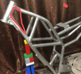
Hub motor as mid (illegalbike) 6000-12000W / 33-35kg

I understand what you are asking now! Mechanically it's the bearings, the magnets are on the outside so should not bother them. Don't remember more than 1000 rpm on a DD. There is a better answer don't remember it now. It's about the motor not design to spin faster. Not that they can't, but not efficiently. Not to say something that heavy to get it spinning 1000's or rpms and then slow it down is another issue. I will look for the answer I think you want.

by Hummina Shadeeba » Oct 27 2021 7:31pm

I mean what is the max rpm the motor can mechanically take before flying apart.(what rpm would be electrically ideal is another question). And I think all the sellers I’ve asked are misunderstanding me too and bet the motor can do way more than 600rpm


It’s 638rpm as they advertise it with the 20” wheel so they surely aren’t answering the question and likely don’t know.

https://www.leafbike.com/products/diy-b ... -1185.html

((They told me they’ve tested it to 930rpm))
 
Hummina Shadeeba said:
How much and how soon
I make a custom semi-finished product with the engine installed, the frame itself, the rotary lever, the rear fixed hub, the chain and all bearings. It is expected that such a set will amount to 990 US dollars

the frame is painted with powder paint in the right color from the catalog, it is possible to assemble the bike entirely

Hummina Shadeeba said:
everywhere selling the motor says its max rpm is 600. I don’t know ur gearing but think u said 2:1 and looks fast. I wonder what rpm you do and why they state 600rpm and if in a built wheel the spoke tension would be added to the force but when running the motor bare as you do.. what you think?

if we are talking about 1500w hubmotor, they come with different windings, for example, a winding of 12 * 5 (12 wires and 5 turns) gives 8.5 kV, which means at 48 volts there will be 408 revolutions per minute, at 72 volts already 612 rpm (idle speed, no load). This is a very traction motor

There is a faster winding, for example, with 3 turns, it has 14 kV, therefore, it can spin up to 14kV * 48V = 672rpm or 14kV* 72V = 1008rpm idle. This is a very high-speed motor

You can always make a high-speed motor from a traction motor if you switch the windings from a star to a triangle
 
Hummina Shadeeba said:
I mean what is the max rpm the motor can mechanically take before flying apart.(what rpm would be electrically ideal is another question). And I think all the sellers I’ve asked are misunderstanding me too and bet the motor can do way more than 600rpm

when the hub motor is in the center of the frame, and not in the wheel, it operates in a very gentle mode and is able to cope with much larger loads.

at the same time, such an arrangement is not as intended by the manufacturers, the characteristics of the work are different and sellers simply will not be able to give recommendations and the right answer
 
ZeroEm said:
I understand what you are asking now! Mechanically it's the bearings, the magnets are on the outside so should not bother them. Don't remember more than 1000 rpm on a DD. There is a better answer don't remember it now. It's about the motor not design to spin faster. Not that they can't, but not efficiently. Not to say something that heavy to get it spinning 1000's or rpms and then slow it down is another issue. I will look for the answer I think you want.

I turned it up to 1350rpm))

on the yellow bike, the 9kV motor was converted into a triangle and became 9kV*1.8 = 16.2kV, the idle speed on a fully charged battery (84V) was 1350rpm and on a dead battery about 1000rpm

I observe a small gyroscopic moment of the flywheel in the center of the frame, I have only positive feelings from this, I feel stability in turns. This effect is not very strong and does not interfere with sudden movements on a bad road. I was satisfied with this result
 
illegalbike said:
Hummina Shadeeba said:
How much and how soon
I make a custom semi-finished product with the engine installed, the frame itself, the rotary lever, the rear fixed hub, the chain and all bearings. It is expected that such a set will amount to 990 US dollars

the frame is painted with powder paint in the right color from the catalog, it is possible to assemble the bike entirely

I imagine you’ll be telling us here when that’s available and looking forward to it.


Yea I meant if the centrifugal force at high speed would be a problem.


I wonder what gear ratio and rpm of the motor would be ideal. At what point the motor is spun so fast the iron losses supersede the copper? The graphs on leaf motor don’t reveal iron losses and just inefficiency from increased current. Tell me if I’m wrong but this graph shows the motor at 13kv getting inefficient above 30 amps.
https://leafbike.com/u_file/images/15_01_05/0a32577ead.jpg. Your kv being 16 I’m guessing could take maybe 35 amps before dropping in efficiency? That seems an awfully low amount of current for it to start to saturate but I guess so. I have my esc programmed to 120 amps with these motors and i can feel changing from 100 to 120 amps it’s a not just going to heat but when looking to make the most efficient drive possible it would be nice to know the no-load losses up at the high erpm you do.
 
Hummina Shadeeba said:
Tell me if I’m wrong but this graph shows the motor at 13kv getting inefficient above 30 amps.
https://leafbike.com/u_file/images/15_01_05/0a32577ead.jpg. Your kv being 16 I’m guessing could take maybe 35 amps before dropping in efficiency?

with my English it is difficult to answer in detail. I repeat that the factory characteristics and tests of hubmotors have little in common with a hubmotor converted into a triangle and operating not DD, but by reducing the gear ratio. The controller on the yellow bike could only output 120 amps of phase current, and I couldn't warm up the motor above 70 degrees - all the time in all those videos I posted. During long ascents, my controller just turned on the protection, but the engine remained lukewarm. The capabilities of the motor in such a frame are higher than what I have already experienced, I will need a more powerful controller to find out its limit
 
When ur frame for sale u think?

With the no load speed current draw at ur highest rpm maybe be enough to figure what gear ratio be ideal for whatever type riding n speed.
 
Just need a gear calculator, get your wheel diameter that you plan on running.

You can play with the Grin's motor simulator.
https://ebikes.ca/tools/simulator.h...p=0&motor=Leaf 5T&kv=16.11&gear=3&tf=34&tr=34
set it up with 3:1 but you can change it to whatever you want, used a leafmotor at 16.11Kv. 40a 72v. 1130rpm loaded.

by Hummina Shadeeba » Oct 30 2021 3:46pm

When ur frame for sale u think?

With the no load speed current draw at ur highest rpm maybe be enough to figure what gear ratio be ideal for whatever type riding n speed.
 
Thanks I’ll try it. With such complications I generally find I can’t get it running. Aha! Yr link has it all thanks.


ZeroEm said:
Just need a gear calculator, get your wheel diameter that you plan on running.


i altered the simulation with a tiny wheel (to get a low load), and a huge voltage and kv (to build up rpm),but still at even 2500rpm it shows 85% efficiency. i dont think its simulating the iron losses and at that speed I think it should be an eddy current meltdown.

https://ebikes.ca/tools/simulator.html?batt=cust_180_0.2_8&cont=cust_130_130_0.03_T&hp=0&motor=Leaf%205T&kv=16.11&wheel=90mm&autothrot=false&throt=100&frame=full
 
You went back to a hub and removed the gearing. The gearing is the point of his build. This motors are not made to spin 2000 rpms. illegalbike rewound the motors to a Y to get more motor speed/rpm.

I tried to keep the chain ring and sprocket the same. You want to change the gear ratio to get your speed. Don't think you will be running a 180v battery or riding a full recumbent. Stick to the norm's of what you run now. Putting the motor in the frame lets you gear the motor like it is in a 20" running a 3T motor at high voltage then gear it down.

If you ever played with wheel sizes, the motor loses efficiency if you try to spin it outside of it's range. If you want a high rpm motor get one. Inrunner. illegalbike stated he is going to try one to see the results. The big hub motors have more low end torque, slower spinning. Don't think your going to spin them 1400 or above with a reasonable setup. Start with looking a the motor's unloaded rpm at a given voltage.

by Hummina Shadeeba » Oct 31 2021 12:54pm

Thanks I’ll try it. With such complications I generally find I can’t get it running. Aha! Yr link has it all thanks.

ZeroEm wrote: ↑Oct 30 2021 5:23pm
Just need a gear calculator, get your wheel diameter that you plan on running.


i altered the simulation with a tiny wheel (to get a low load), and a huge voltage and kv (to build up rpm),but still at even 2500rpm it shows 85% efficiency. i dont think its simulating the iron losses and at that speed I think it should be an eddy current meltdown.

https://ebikes.ca/tools/simulator.html? ... frame=full
 
Regardless of the gear ratio the motor is spinning 2500rpm with a small load yet still showing a very high efficiency. Maybe that’s right but I’d think that motor with its many poles and high erpm per rpm would start to sink into inefficiency from eddy currents and not be efficient at such a speed. No?


My point is to figure what gear ratio is most efficient. This is a big motor that would generally be slowly spun and he’s spinning it 2x faster with the possibility of 3x faster. Copper losses should therefore go down and iron up with this gearing and trying to figure rpm is ideal. What is the no-load current draw even at 1000rpm I wonder.


I don’t want to distract from the topic and I’m here because I really like this bike. I think it’s worth knowing what speed the motor could safely be spun and what gear ratio is ideal. They will do a 3T version or I could wind the motor or other places will to whatever kv and maybe worth doing


This is what I’m talking about:
https://endless-sphere.com/forums/viewtopic.php?t=41230
 
I know what you are saying. illegalbike rewound his motors to the the rpm.
I would not and see the advantage of his design as you could run a 29" wheel and gear it like you have a 20" or 16" wheel. That would give a lot of benefit and removing the unsprung weight with the torque and quietness of a DD. If you want a fast spinning motor just get one.
 
i dont think you can get a faster spinning motor. I think he has the 3T from leaf and reterminated it to delta. i think if you want it any faster it would have to be rewound. (i just wrote them to see if they will sell unwound and they said have to buy 100) or else it's doing an inrunner and thats a different bike.

it somewhat loses the quietness of the DD but otherwise i agree with you. i dont know what your "I would not" is meaning. im saying maybe its better to gear it 3:1..maybe its better geared 2:1.. ...maybe its better geared 4:1. im curious. I think I have the 3T motor and i guess could map out the no-load losses up to 70v and whatever rpm that is but was hoping someone had done it.
 
miro13car said:
incredible simplicity of this build
so what are advantages of having motor at the cranks versus build into rear wheel.

Unsprung weight is low in rear wheel (better for suspension:much better ride quality);
Better center of gravity;
Gearing can be adjusted to optimum;
Cooling is better.
 
illegalbike does not have a cassette. Not sure with his setup but most would put the sprockets on the left side. Don't think he has pedles.
y miro13car » Nov 05 2021 4:24pm

but what about rear wheel cassette
can you still change motor-rear sprocket gear ratio?
 
During the tests, we tore the frame on a big drop, and from now on I will be strengthening this place

[img=https://illegalbike.ru/uploads/for_web/crash1.JPG][/img]
[img=https://illegalbike.ru/uploads/for_web/crash2.JPG][/img]
[img=https://illegalbike.ru/uploads/for_web/crash3.JPG][/img]
[img=https://illegalbike.ru/uploads/for_web/crash4.JPG][/img]
[img=https://illegalbike.ru/uploads/for_web/crash5.JPG][/img]
[img=https://illegalbike.ru/uploads/for_web/crash6.JPG][/img]
 
illegalbike said:
mxlemming said:
Mr illegal, could you share some details of how you've constructed the main pivot? Looks very tidy, but the bearing axial loading etc?

[youtube]2P5jcQxCzqM[/youtube]

Cheers dude! That was a really neat video! Thanks for that effort.

And bad luck on smashing that wheel and cracking the frame. But props for sharing! More metal there I guess. They always crack at the head tube.
 
[img=https://illegalbike.ru/uploads/for_web/repair1.jpeg][/img]
[img=https://illegalbike.ru/uploads/for_web/repair2.jpeg][/img]
[img=https://illegalbike.ru/uploads/for_web/repair4.jpeg][/img]
[img=https://illegalbike.ru/uploads/for_web/repair5.jpeg][/img]
[img=https://illegalbike.ru/uploads/for_web/repair6.jpeg][/img]
 
illegalbike said:
[img=https://illegalbike.ru/uploads/for_web/repair1.jpeg][/img]
[img=https://illegalbike.ru/uploads/for_web/repair2.jpeg][/img]
[img=https://illegalbike.ru/uploads/for_web/repair4.jpeg][/img]
[img=https://illegalbike.ru/uploads/for_web/repair5.jpeg][/img]
[img=https://illegalbike.ru/uploads/for_web/repair6.jpeg][/img]

My thought is that you should have between the top and down tubes a plate that takes the shear force between them.

At the moment, while your joints are stronger, the same load that's caused your failure exists.

I just spotted the stand and nearly died. You stole that from a child :eek:

Screenshot_20211112-124235-584.png
 
Back
Top